STEM Exploration: The Smart Eco-House Prototype
The "Snap Circuits and IoT" project is a comprehensive educational activity designed to introduce children (ages 10-14) to the concepts of sustainable architecture and the Internet of Things (IoT). By combining the accessibility of Snap Circuits with the computational power of the ESP32, kids build a miniature "Eco-House" that monitors its own environment and can be controlled remotely.
Educational Core: Energy Efficiency through Awareness
The project focuses on teaching three pillars of modern energy efficiency:
- Passive Monitoring: Using a DHT11 sensor to track temperature and humidity. Understanding these variables helps kids learn why certain appliances (like AC or humidifiers) are needed and how insulation can reduce their use.
- Luminous Optimization: An LDR (Light Dependent Resistor) tracks natural illumination. This teaches kids about house orientation (e.g., south-facing windows) and the potential for automated lighting that turns off when the sun provides enough light.
- Active Management: By integrating the Blynk app, children can "command" their house from their parents' tablets or phones, turning off miniature appliances from another room to simulate energy saving.
Advanced Hardware: ESP32 and Snap Circuit Integration
While Snap Circuits are traditionally used for simple battery-powered projects, this activity bridges them to the digital world:
- Crocodile Cable Bridging: Custom "Crocodile-to-Jumper" cables allow the ESP32's digital and analog pins to interact with the Snap Circuit grid safely.
- Industrial IoT logic: The project uses the ESP32 specifically for its dual-core processor and built-in WiFi, ensuring the house remains connected even as complex sensor data is being processed.
- 3D Printed Engagement: To add real-life context, the project includes 3D printable covers for Snap components, transforming generic LEDs into miniature "Televisions," "Stoves," and "Washing Machines."
Preparing for a Sustainable Future
This activity moves beyond just "building a circuit" to "solving a problem." By designing, coding, and testing their Smart House, kids gain the critical thinking skills needed to tackle future environmental challenges through technology.
In this activity kids will learn how IoT can contribute to energy efficiency of a house.
They will be setting up a miniature house using snap circuits, and will program the different appliances via ESP32, notably to:
monitor environmental parameters (temperature humidity) in real time control appliances remotely via Blynk.


INTRODUCTION
Energy efficiency can be affected by the position of the house with respect to the sun, the prevailing wind, etc. Thus, for example, to increase energy efficiency, one will want to position a house facing towards the south, so that the sun rays can provide natural illumination.
Other factors to take into consideration in order to maximize energy efficiency are directly related to the appliances you use.
Here’s a few tips:
use smart appliances, for example lights bulbs that go on at night and automatically turn off during the day use smart plugs equipped with an on off button that can be programmed to turn on and off at specific times. hook your appliances to the internet so that you can control them remotely from any location.
Supplies:
- 1x ESP32 board + usb cable
- crocodile cables
- 1x DHT11 sensor
- 1x LDR sensor
- 1x 10kohm resistor
- Breadboard
- jumper wires
- snap circuits
- miniature house
Step 1: Setting Up the Miniature House
To begin with, kids will need to build or assemble a miniature house. They can build one using cardboard, or you can laser cut them in advance, using for example a 3mm thick MDF board. Here’s the design of a miniature house, ready for laser cut.
Step 2: Monitoring Temperature, Humidity and Light With Blynk
Kids will be setting up a Blynk project that enables them to monitor the parameters recorded by temp/humidity and light sensors located in their miniature house.
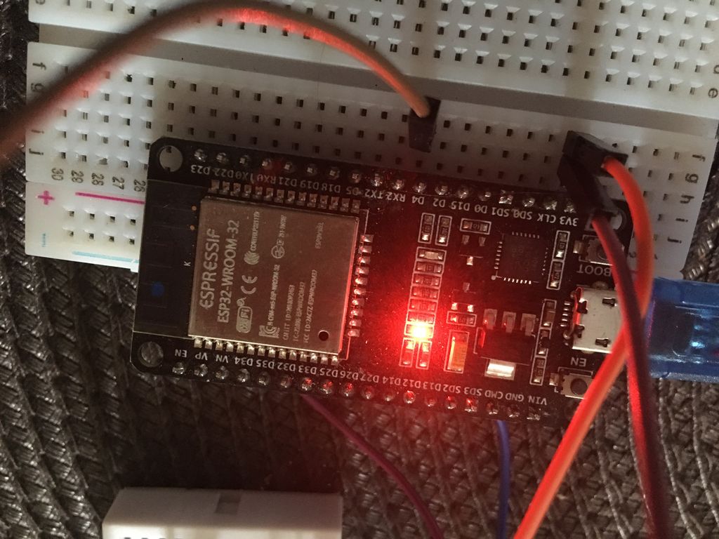
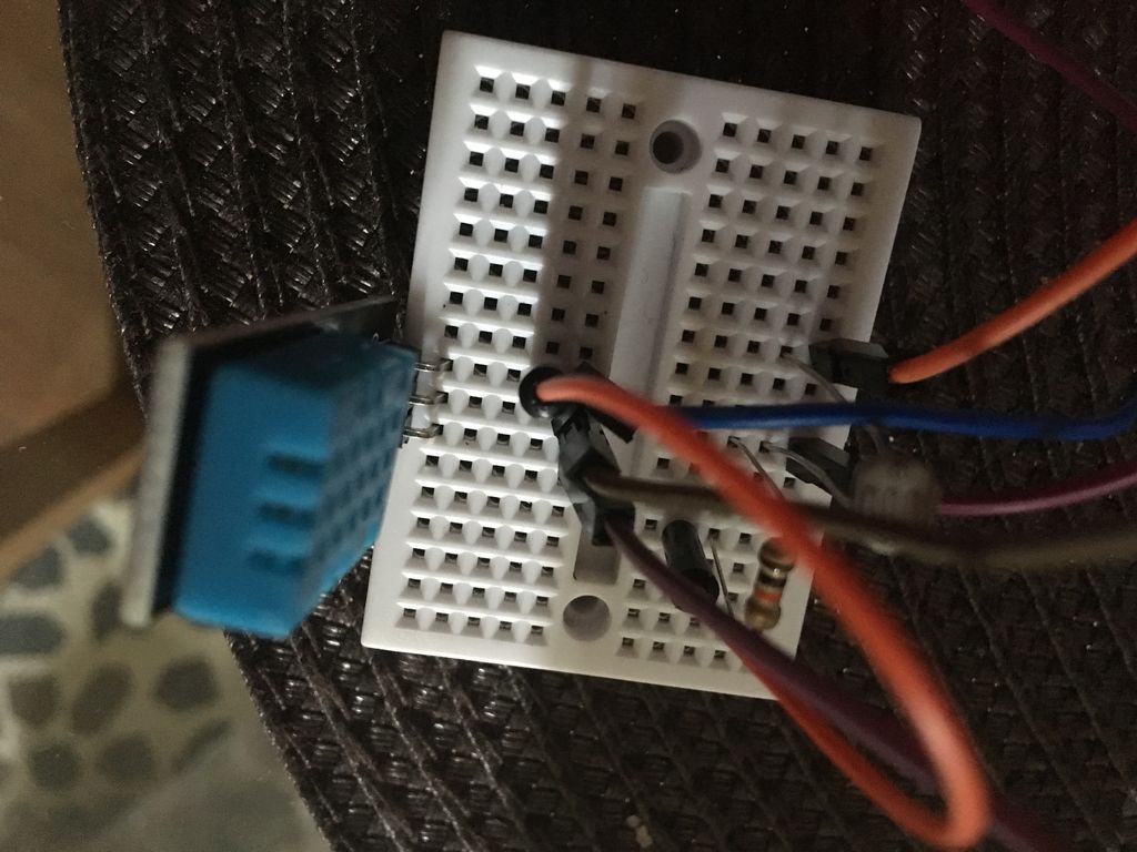
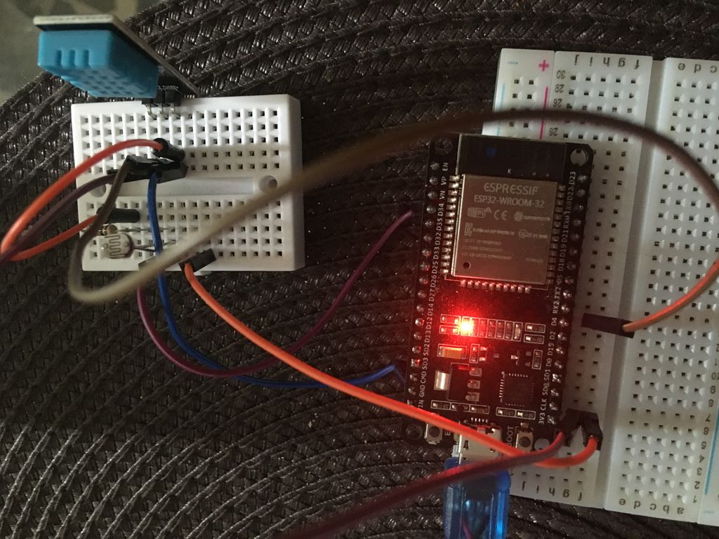
First, hook up the LDR snap and the DHT snap to the ESP32 board. connect Data pin of the DHT sensor to pin 4 on the ESP32 board. Connect the LDR snap to pin 34 on the ESP32.
Next, you ll have to create a Blynk project and configure it to display the values recorded by the temp/hum sensor.
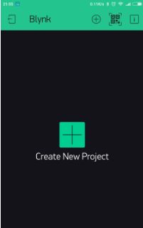
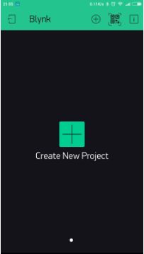
CREATE A NEW PROJECT IN THE BLYNK APP
After you’ve successfully logged into your account, start by creating a new project.
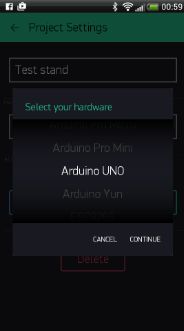
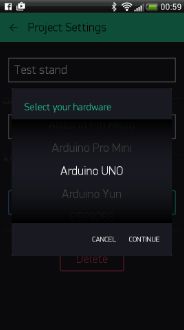
CHOOSE YOUR HARDWARE
Select the hardware model you will use. If you are following this tutorial you ll probably be using an ESP32 board.
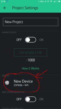
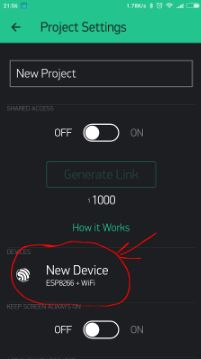
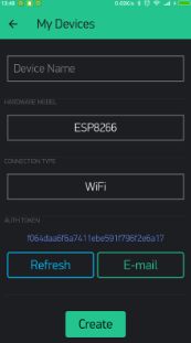
AUTH TOKEN
Auth Token is a unique identifier which is needed to connect your hardware to your smartphone. Every new project you create will have its own Auth Token. You’ll get Auth Token automatically on your email after project creation. You can also copy it manually. Click on devices section and selected required device
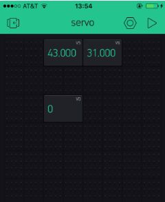
CONFIGURE VALUE DISPLAY WIDGETS
Drag and drop 3 value Display widgets.
configure them as follows:
1) set input as V5, from 0 to 1023. Set refresh interval as Push2) set input as V6, from 0 to 1023. Set refresh interval as Push
3)set input as V0, from 0 to 1023. Set refresh interval as Push
The first display widget will be receiving humidity values from the DHT sensor, and displaying them on the app; the second display widget will be receiving temperature values over wi-fi, the third display widget will be displaying values of light recorded by the LDR sensor.
PROGRAM THE ESP32 BOARD
Launch Arduino IDE, select the correct board and port -under the “Tools” menu-. Paste the code below into the software and upload it onto the board.
Step 3: Control Miniature Appliances Remotely Via Blynk
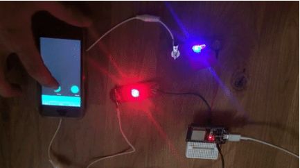
The last part of the activity will be about controlling the electrical appliances one by one remotely via the blynk app.
Each miniature house will need to include at least one miniature light bulb as well as another appliance (ex. miniature 3D printer, miniature oven).
Being able to remotely control one s appliances gives the user the obvious advantage of being able to choosing when they're running and when they aren’t, thus contributing to saving energy and making the miniature house as energy efficient as possible.
We've designed a number of 3D printable miniature electronic appliances that can be placed on top of a snap component. You can for example imagine to place the miniature oven on top of a Led or a miniature 3D printer on top of a mini vibrating motor snap, thus emulating real-life operations of those appliances.
Find all appliances available for 3D printing by clicking on the links below:
This activity will require the Blynk application. So, first download Blynk on your smartphone.
CREATE A NEW PROJECT IN THE BLYNK APP
After you’ve successfully logged into your account, start by creating a new project.
CHOOSE YOUR HARDWARE
Select the hardware model you will use. If you are following this tutorial you ll probably be using an ESP32 board.
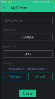
AUTH TOKEN
Auth Token is a unique identifier which is needed to connect your hardware to your smartphone. Every new project you create will have its own Auth Token. You’ll get Auth Token automatically on your email after project creation. You can also copy it manually. Click on devices section and selected required device, And you’ll see token
PROGRAM THE ESP32 BOARD
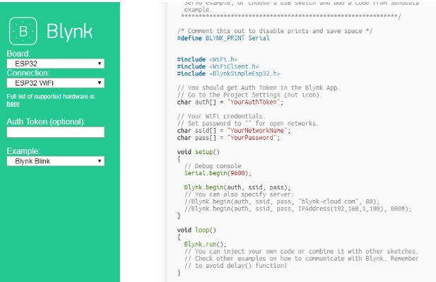
Head to this website, select your hardware, the connection mode (ex. wi-fi) and choose the Blynk Blink example.
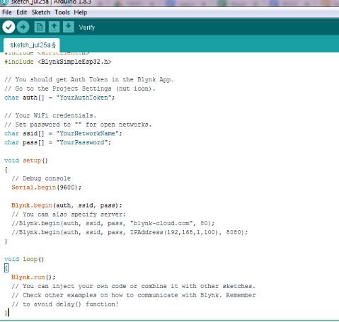
Copy the code and paste it on Arduino IDE (prior to that, make sure you select the correct board and the correct port - under “Tools”-).
Replace “YourAuthtoken” with the token available on the app, replace “YourNetworkName” and “YourPassword” with your wi-fi credentials. Finally, upload the code onto the board.
SET UP THE BLYNK APP
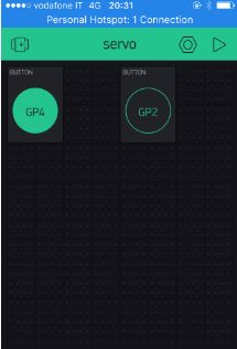
In your Blynk project, choose button widgets, as many buttons as you have snaps to control remotely. In our example we’ll add two buttons widgets since we have two snap parts to control (both are LEDs).
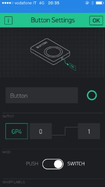
Next select the first button and, under output, choose the port to which one of your snap is connected to the ESP32 board (ex. GP4). Make sure to have 0 and 1 next to GP4, just like in the image at the end of this step. You can also choose whether the button will function in mush or switch mode.
Do the same for the second button, only this time connect to the relevant ESP32 pin (ex. GP2).

This tutorial has been produced as part of the DEEDU project, co-financed by the Erasmus + Programme of the European commission. Project n°: 2018-1-FR02-KA205-014144.
The content of this publication does not reflect the official opinion of the European Union. Responsibility for the information and views expressed therein lies entirely with the authors.
For more information, email us at info@digijeunes.com.