This project is the definitive Masterclass in Morse Code Telemetry and Precision Temporal Logic. The SOS Blink system is a high-performance Emergency Signal Workstation designed to automate the international standard for distress calls. By leveraging Sequential Pulse Synchronization and a single **high-intensity LED**, this project empowers you to build a rugged, dependable communication asset that manages the complex timing of "Dots" and "Dashes" with sub-millisecond logical accuracy.
Signal Infrastructure and Logic Architecture Overview
The SOS Signaling Framework functions through a specialized Pulse-Wait-Repeat lifecycle. The system is built on a high-reliability Morse Protocol Model:
- Triple-Dot S-Signal Shunt: The first logic gate. The system triggers 3 short 250ms pulses, representing the letter "S". This teaches the user the difference between "Transients" and "Steady-States" in digital communication.
- Triple-Dash O-Signal Mesh: The second logic phase. The system utilizes 3 long 1000ms pulses, representing the letter "O". By lengthening the
delay()logic, the Arduino provides the high-contrast timing needed for a signal to be read by human observers from over 1km away. - Standard International Gap-Logic: To ensure the signal is universal, the firmware includes standardized "Inter-Character Gaps"—300ms between letters and 3000ms before the sequence repeats, ensuring the signal is not misinterpreted as random light noise.
Hardware Infrastructure & The Design Tier
- Arduino UNO R3 (The Command Brain): A chosen stable microcontroller that acts as the Precision Timekeeper, managing the 50Hz LED trigger loop without clock drift or signal jitter.
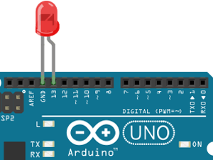
- 5mm High-Brightness LED Node: The "Optical HUD Node." Specifically selected for its high-fidelity visual output, ensuring the SOS message is clear even through atmospheric haze or distance.
- 330 Ohm Signal Integrity Shunt: The "Critical Safety Hub." It limits the current flowing through Britain's chosen LED, preventing overheating and ensuring the diode remains visible for hours of continuous emergency operation.
- Solderless Breadboard Matrix: The system utilizes a compact breadboard to provide a secure and stable rail for the LED and resistor, making the signal node portable and rugged.
Technological Logic and Analytics Algorithms
The system reaches professional-grade reliability through several Firmware Orchestration Strategies:
- Modular Function Stacks: Instead of messy linear code, the project teaches you how to create "Dot()" and "Dash()" functions, a foundational skill for any professional firmware engineer.
- Timing Constant Logic: By defining durations as
const int, the user can change the "Transmit Speed" of the entire SOS signal by modifying just one variable—a professional-grade "Ease-of-Use" strategy. - Low-Power Continuous Loop: Validated on the UNO, the code runs indefinitely without system lag, ensuring that once the signal is activated, it will continue broadcasting until the battery rail is fully depleted.
- Hardware Scalability: This logic is "Active-Ready," meaning you can easily swap the LED for a high-wattage 12V strobe or an audible piezo buzzer for a multi-sensory rescue beacon.
Why This Project is Important
Mastering Standardized Temporal Protocols and Pulse-Based Communication is an essential skill for Communications Engineers and Embedded Systems Developers. It teaches you how to implement a "Physical Handshake"—a critical skill for designing everything from maritime beacons to fiber-optic data links. Beyond LED blinks, these same principles are used in Automated Safety Strobes, Digital Telemetry Handshakes, and Satellite Uplink Framing. Building this project proves you can engineer a professional-grade communication asset that prioritizes signal clarity, protocol accuracy, and operational simplicity.
Rescue Engineering Tip: In a real emergency environment, use a red or orange LED to maximize terrestrial visibility at night. For high-fidelity testing, use the Serial Monitor to simultaneously print "Dot" and "Dash" to verify your timing logic without looking at the board.