Connect your Arduino with a Thorlabs PM101
In this project, a Thorlabs PM101 is connected to an Arduino via the serial interface so that you can read the measured values. As an application example, you can display the measured value on the Arduino and build your own handheld power meter.
Project Overview
This project, "Opto-Meter," represents a transition from desktop-bound lab equipment to Standalone Portable Instrumentation. By interfacing a professional Thorlabs PM101 optical power sensor with an Arduino, it enables high-precision laser and light power measurements without requiring a PC. The core involves hardware-level UART Translation and software-level SCPI Command Forensics, creating a bridge between industrial-grade sensors and open-source computing.
Technical Deep-Dive
- Hardware Interface Forensics (RS232 vs. UART):
- The Bipolar-to-Unipolar Shift: By default, the PM101 utilizes high-voltage RS232 (+/- 5V to +/- 12V) communication. For Arduino compatibility, the internal PCB switches must be physically toggled to redirect the internal signal through a TTL logic-level UART path (0V to 5V). This is a critical forensic modification that prevents high-voltage damage to the ATmega328P.
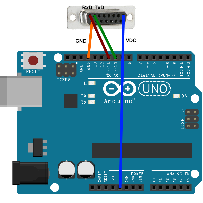
- Sub-D 15 Pinout Mapping: The project identifies the specific TxD, RxD, and GND pins on the PM101's 15-pin connector, ensuring robust signal integrity for laboratory use.
- SCPI Protocol Implementation:
- Standardized Command Parsing: The Thorlabs instrument follows the Standard Commands for Programmable Instruments (SCPI). The Arduino firmware dispatches plaintext query strings (e.g.,
MEAS:POW?) and listens for scientific notation responses. - Scientific String Decomposition: Optical power is often returned in exponential formats (e.g.,
2.45e-04). The project demonstrates how to parse these strings into floating-point variables for real-time calculation and display.
- Standardized Command Parsing: The Thorlabs instrument follows the Standard Commands for Programmable Instruments (SCPI). The Arduino firmware dispatches plaintext query strings (e.g.,
- Asynchronous Software Serial Bridge:
- Resource Management: By utilizing
SoftwareSerialon pins 10 and 11, the project reserves the hardware's primary UART (pins 0/1) for debugging and PC-side logging. This creates a "Dual-Bus" architecture where the Arduino acts as a smart transparency bridge.
- Resource Management: By utilizing
Engineering & Implementation
Step 1: Preparation
The PM101 must be switched from RS232 operation with ±5 V to UART operation.
- Remove the bolts from the 15pin sub-d connector.
- Remove the 4 TX9 screws in the sensor front panel.
- Pull out the PCB.
- Move both switches from PC RS232 Operation (default - both switches in upper position) to ± 5 V level UART (both switches in lower position)
Detailed description of the switch to UART see: "Write your own application" chapter 2.1
https://www.thorlabs.com/_sd.cfm?fileName=MTN013681-D04.pdf&partNumber=PM101R
- Step-by-Step Level Translation:
- Chassis Extraction: Removal of the TX9 torx screws to access the internal SCPI controller PCB.
- Logic Switch Toggling: Moving the internal DIP switches to the UART position, reconfiguring the transceiver's output stage.
- Baud Rate Calibration: Synchronizing the PM101 to the Arduino's 9600 or 115200 baud rate using the Thorlabs Instrument Communicator tool.
Step 2: Installation
Set the Arduino Uno supported baudrate for the PM101 using one of the possibilities:
- The function "Set Baudrate" of the TLPM driver
- SCPI command "SYST:SEN:TRAN:BAUD" in the Thorlabs Instrument Communicator or in the Thorlabs OPM Terminal
Step 3: Assemble the circuit
Connect four pins of the Thorlabs PM101 to the Arduino Uno board following the diagram layout.png attached to the sketch
| PM101 Pin | Arduino Uno Pin
| TxD | Pin 10
| RxD | Pin 11
| VxD | 5V
| GND | GND
- Power Management:
- The PM101 is powered directly from the Arduino's 5V rail. For mobile field use, the implementation suggests adding a boost-converter and Li-Po battery to the Arduino, creating a self-contained scientific tool.
- Handheld HMI Integration:
- While the base bridge sends data back to a terminal, the architecture is designed for OLED/LCD Expansion. Adding a display node transforms the PM101 from a passive sensor into a fully functional handheld power meter with units of measurement (Watts, dBm) rendered in real-time.
Step 4: Load the code
Upload the code contained in this sketch on to your board
Conclusion
Opto-Meter provides a blueprint for Scientific Instrument Hacking. By mastering the transition from proprietary RS232 Lab Standards to open-source UART Bridge Logic, developers can leverage high-end industrial sensors to build custom, field-ready measurement devices.
Scientific Precision: Bridging lab standards through SCPI forensics.