This project is about the magnificent IC / module called "MSGEQ7". It's really fun to use albeit a little bit confusing when it comes to the coding part. I made it to test what I can do with it and to know whether if I can use it on my future projects.
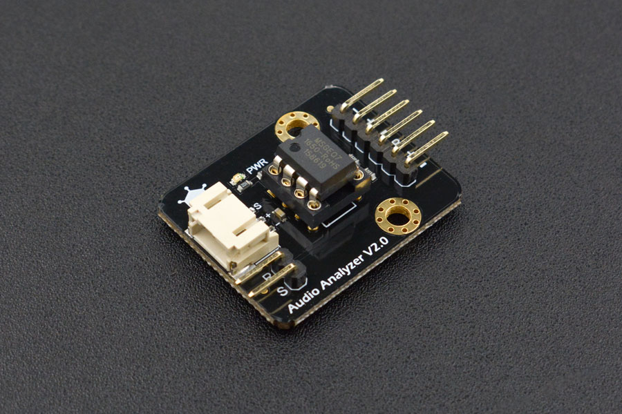
This is a 7 Band Audio Analyzer Module from DFRobot.
"This Audio Analyzer module features the MSGEQ7 graphic equalizer display filter.It will give your arduino ears. Sound is broken down into seven frequency bands and the peak level for each band can be read. The seven frequencies measured are as follows: 63Hz, 160Hz, 400Hz, 1kHz, 2.5kHz, 6.25kHz and 16kHz. This Audio Analyzer module can be used to create sound visualizers, detect patterns in music or add sound activation to your microcontroller." - DFRobot Website. (https://www.dfrobot.com/product-514.html)
It collects/reads sound frequency like a Sound Sensor Module. But it does it digitally when connected to a headphone jack. Whenever a certain peak or threshold has been reached, it activates the LED/s and turns it on. Sound frequency data can also be seen by using the Serial Plotter on the Arduino IDE Software.
Technical Deep-Dive
- Hardware FFT (MSGEQ7 IC):
- Frequency Filtering: Conventional microcontrollers struggle to perform high-resolution Fast Fourier Transforms (FFT) in software while simultaneously driving displays. The MSGEQ7 solves this by using seven internal switched-capacitor filters. It breaks the audio spectrum into fixed center frequencies: 63Hz, 160Hz, 400Hz, 1kHz, 2.5kHz, 6.25kHz, and 16kHz.
- Strobe & Reset Timing: The Arduino controls the IC using two digital pins: RESET and STROBE. A Reset pulse tells the IC to look at the first band (63Hz). Subsequent Strobe pulses cycle through the remaining six bands. For each pulse, the IC outputs a DC analog voltage on its
OUTpin, which is directly proportional to the peak amplitude of that frequency band.
- Analog-to-Digital Mapping:
- The Arduino's 10-bit ADC reads the voltage (0V to 5V) and converts it to a numerical value between 0 and 1023.
- The firmware uses the
map()function to convert this intensity into the number of LEDs lit in each frequency's column (e.g., a volume of 500 might light up 2 LEDs, while 1000 lights up all 4).
- Visualizing via Serial Plotter:
- By printing the seven values to the Serial port separated by tabs or commas, the developer can use the Arduino IDE Serial Plotter to see seven scrolling graphs of the audio bands. This is a critical debugging step to ensure the audio input is "peaking" at the correct levels.
- Signal Conditioning:
- The module includes decoupling capacitors to remove DC offset from the input. Using a 3.5mm Audio Splitter allows the source (like a smartphone) to feed both the analyzer and a set of speakers simultaneously without signal degradation.
Engineering & Implementation
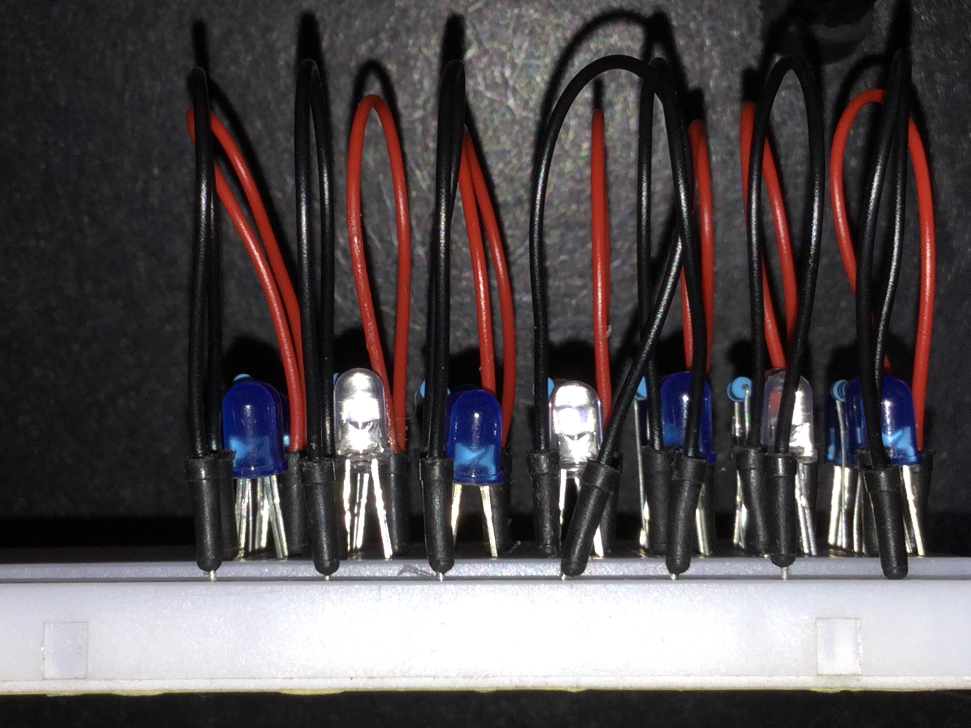
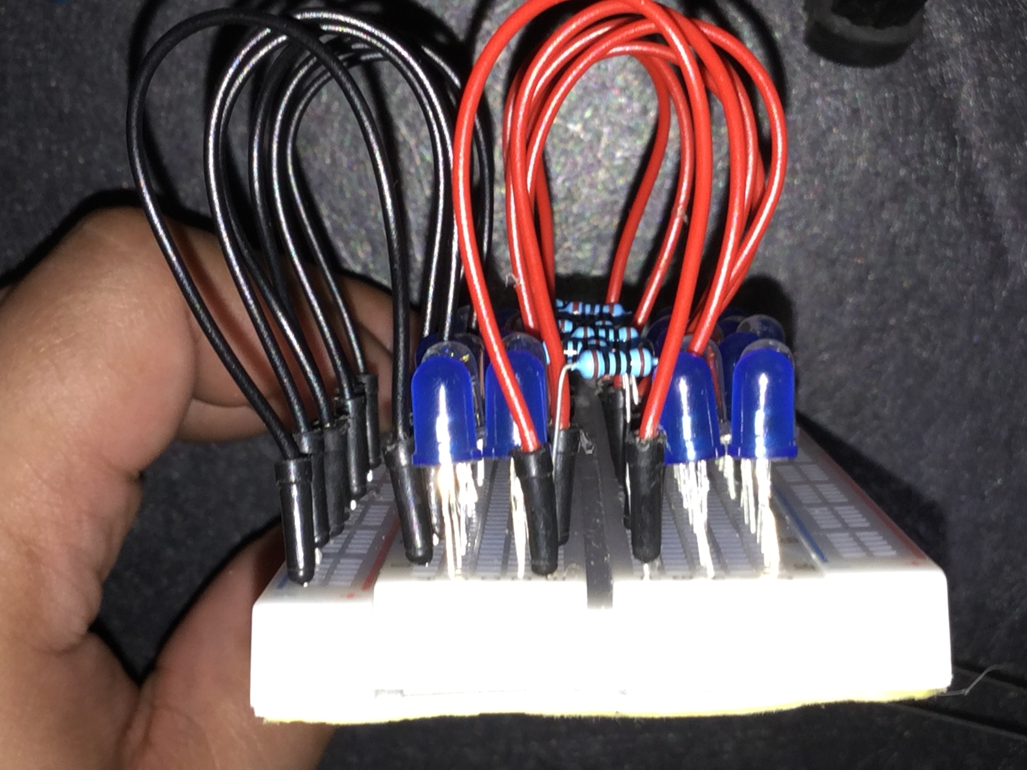
- LED Array Configuration: Controlling 28 LEDs requires either direct pin management on an Arduino Mega or optimized wiring on a Uno. The "Basic" approach uses current-limiting 100 ohm resistors to ensure the LEDs are bright enough to be reactive while keeping the total current draw within the limits of the Arduino's power rail.
- Thresholding Logic: The code includes a "Noise Floor" variable. This ensures the LEDs don't flicker when there is silence or low-level background noise, only reacting when a significant "Peak" is detected.
- Speed & Latency: Because the MSGEQ7 handles the filtering in hardware, the visual response is near-instantaneous (less than 1ms latency), providing a perfectly "tight" synchronization between the bass kick and the first LED column.
- Integration Tip: For better aesthetics, place the LEDs behind a diffuser (like white acrylic) to create a soft "Glow" effect, turning a simple circuit into a professional-looking entertainment system accessory.
Social Media Links To Follow (I mean, if you want to): Facebook - https://fb.me/HeathenHacks Twitter - https://twitter.com/HeathenHacks Instagram - https://instagr.am/HeathenHacks