I originally used this project to monitor the temperature and humidity for monitoring 3D printing filament storage containers.
The original project has many more features that I will include in another tutorial but for this one I wanted to keep it as simple as possible for anyone starting out or looking for something like this to incorporate to their own project. For the same reason I also kept the wiring to a minimum so not even a bread board is required.
The projects shifts back and forth between temperature and humidity displayed on the 16x2 LCD display.
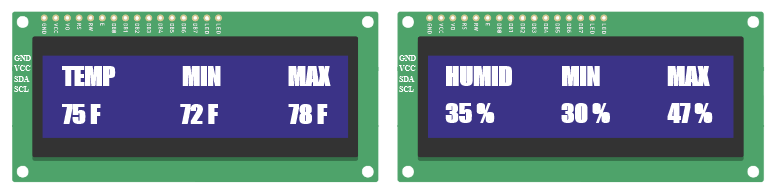
- Displays the current temperature in Fahrenheit
- The minimum recorded temperature
- The maximum recorded temperature
- Displays the current Humidity
- The minimum recorded humidity
- The maximum recorded humidity
The minimum and maximum values are from the time the Arduino board is powered on and updated on each loop.
Archival Telemetry: Min/Max Humidity LCD
A standard DHT11 project is completely amnesiac; it tells you it's 25°C right now, but it has no idea what happened at 3:00 AM while you were asleep. The Temperature & Humidity Min/Max Logger forces the programmer to grasp variable permanence. By constructing comparative 'High-Water-Mark' logic traps, the Arduino actively memorizes the absolute thermal extremes for massive greenhouse or incubation arrays.
The High-Water Mark Logic Triggers
The core of the code relies on initializing two floating-point arrays outside the loop().
float maxTemp = -100.0;float minTemp = 100.0;- The Relentless Comparison Engine: Every two seconds, the DHT sensor reads the current room.
float currentTemp = dht.readTemperature(); if (currentTemp > maxTemp) { maxTemp = currentTemp; // The New King is crowned! } if (currentTemp < minTemp) { minTemp = currentTemp; // The New absolute zero! } - As the day goes from freezing night to scorching noon, these two variables are continually, mathematically overwritten, capturing the extreme boundaries mathematically.
Pushing to the UI and EEPROM
The user navigates the 16x2 I2C Display using a physical button toggle.
- Pressing the UI Button switches the LCD from "Live Data" mode to "All-Time Records" mode.
- The Memory Erasure Trap: If the power goes out, the SRAM forgets the
maxTempandminTempentirely. - Advanced Execution: The code can utilize the
<EEPROM.h>native library. Every time a newmaxTempis recorded, the Arduino can burn the float directly into its physical ROM hard drive!EEPROM.put(0, maxTemp); - When the Arduino boots back up from a power outage, it can instantly retrieve the permanent records:
EEPROM.get(0, maxTemp);, retrieving the historical data flawlessly!
Required Hardware
- Arduino Uno R3 or compatible board (Excellent built-in 1KB EEPROM memory).
- DTH11 Humidity / temperature Sensor Module
- LCD 16x2 display and I2C
- 5 male to female jumper wires
- 2 female to female jumper wires
- Optional: Tactile Push Buttons to act as physical menu-toggle systems (utilizing
INPUT_PULLUP).
Required Libraries
dht.h > DHT sensor library - Arduino Reference
LiquidCrystal_I2C.h > LiquidCrystal I2C - Arduino Reference
Helpful points prior to starting
Because this is intended for a beginner or someone that has not yet used this hardware in this project previously, I am adding these two brief sections with information on the Temperature/Humidity module and the I2C used to connect the LCD to the Arduino board.
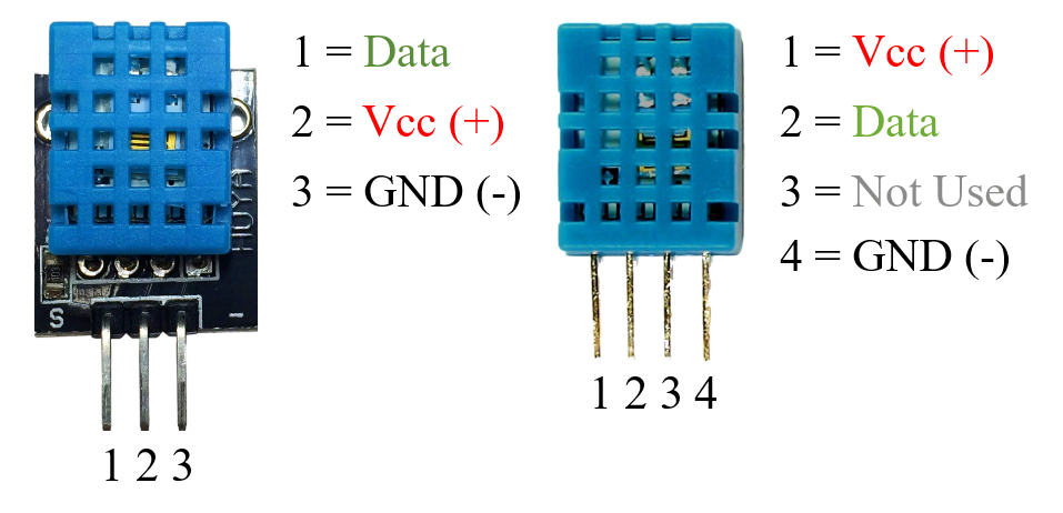
Temperature/Humidity Module
I like using the distinction between “Sensor” and “Module” for the simple reason that they distinctly different and have different connector pins that can easily confuse someone.
For example, the Temperature/Humidity “Sensor” has 4 pins and the Temperature/Humidity “Module” has 3. This might not seem like a big deal but for someone that has never used either one before, it can be confusing as to which pins are the ones that are used.
Additionally, one of the benefits of using the “Module” over the “Sensor” is that the module has a filtering capacitor and pull-up resistor inbuilt. If using just the sensor it is very likely that you will need to provide those as additional parts to your project.
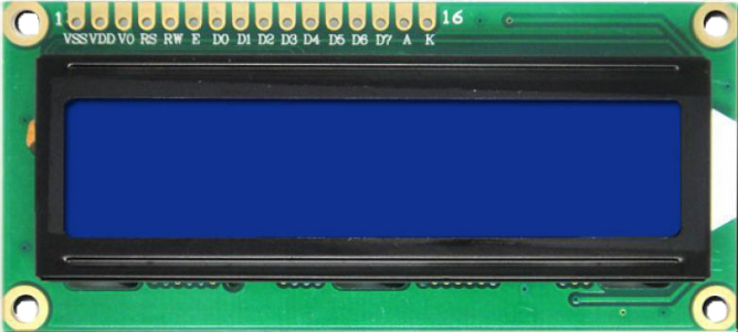
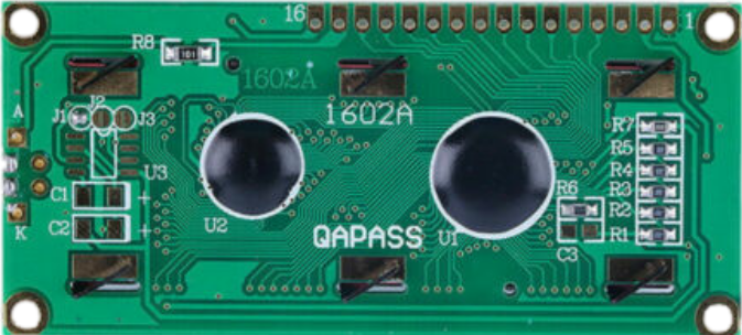
16x2 LCD Display
There are many generic 16x2 LCD displays and any one should work fine. The most obvious differences are the displayed fore and backgrounds colors. The most popular ones feature black text on a green background and white text on a blue background. I use the white text on blue background mainly because I find it easier to read the display.
Below are the images of the 16x2 Display front and back illustrating the 16 pins that connect to the I2C.
I2C as an LCD “Backpack”
The main reason to use an I2C to connect your LCD display to an Arduino board is mainly simplicity of wiring.
It quickly becomes very obvious which method is more convenient when considering whether to use or not use the I2C.
Not using I2C
- Breadboard
- Average of about 16 jumper wires
- External potentiometer
- External resistor
Using I2C
- 4 jumper wires
You can purchase these separate if you have some extra LCD displays laying around and you have the ability to solder them on to the back of the LCD circuit board or you can do as I did and purchase the LCD with the I2C already attached.
Looking at the I2C itself you will notice a few features like the connectors, the blue potentiometer and the jumper.
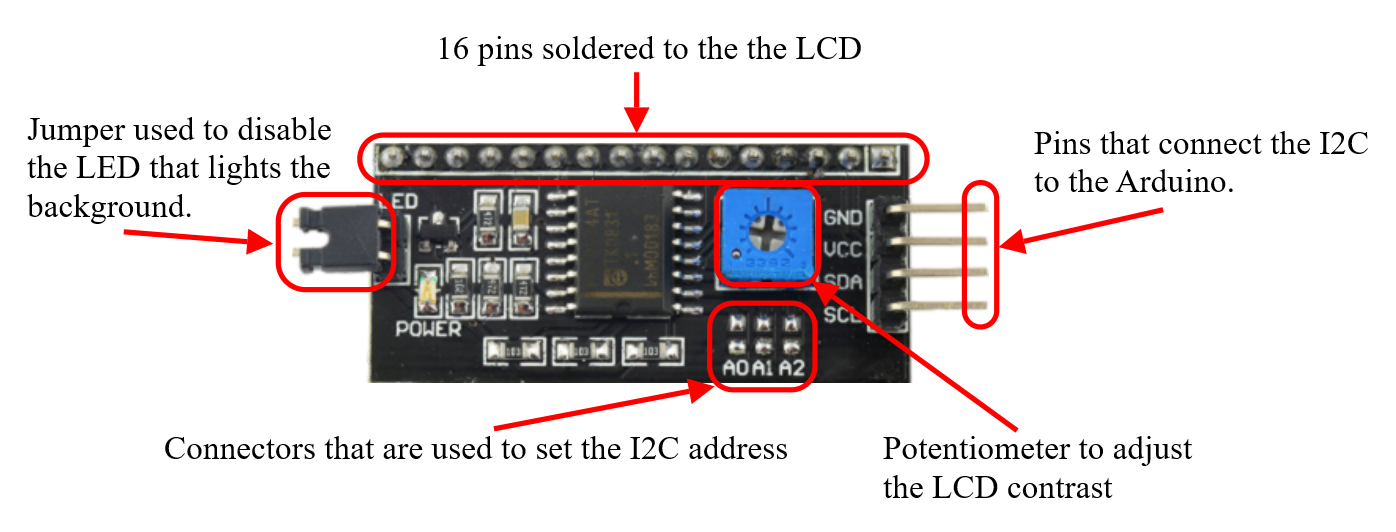
One common misconception that I often hear is the function of the potentiometer on the back of the I2C module. This pot is used to adjust the contrast of the text not the illumination level of the background light.
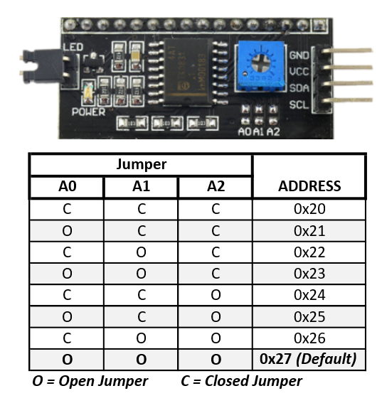
I2C Address
If you are using more than one display in your project of other I2Cs you will need to set the address on the I2C so they can all communicate with the Arduino board. This is accomplished by “shorting” small soldered tabs labeled A0, A1 and A2 and assigning each their own individual address. By default, most LCD I2Cs come with the default address of 0x27.
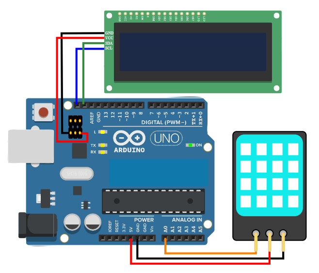
Connecting the hardware
This is probably the easiest part of the project. First, we’ll connect the DHT11 Module and then the I2C that is connected to the LCD display.
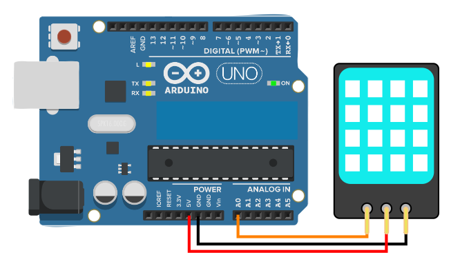
DHT11 Module
Step 1 - With a male/female jumper wire connect the female side to pin #1 (data pin) of the temperature/humidity module and connect the male side of the jumper to the Arduino’s A0 pin.
Step 2 - With a male/female jumper wire connect the female side to pin #2 (Vcc pin) of the temperature/humidity module and connect the male side of the jumper to the Arduino’s 5V pin.
Step 3 - With a male/female jumper wire connect the female side to pin #3 (GND pin) of the temperature/humidity module and connect the male side of the jumper to the Arduino’s GND pin.
When completed it should look like this.
16x2 LCD and I2C
Step 1 - With a female/female jumper wire connect one of the female ends to the GND pin of the I2C module and connect the other female side of the jumper to the Arduino’s GND pin on the ICSP header.
Step 2 - With a female/female jumper wire connect one of the female ends to the Vcc pin of the I2C module and connect the other female side of the jumper to the Arduino’s 5V pin on the ICSP header.
Step 3 - With a female/male jumper wire connect the female end to the SDA pin of the I2C module and connect the male side of the jumper to the Arduino’s SDA pin.
Step 4 - With a female/male jumper wire connect the female end to the SCL pin of the I2C module and connect the male side of the jumper to the Arduino’s SCL pin.
If incorporating this into your own project keep in mind that some Arduinos have internal connections between SDA pin and analog pin A4 and SCL pin and analog pin A5.
When completed it should look like this.