Introduction
Having recently upgraded my PC to enable it to run MS FS2020, I was inspired to improve the controls I was using. A keyboard does not really have the right feel for flying and I wanted to upgrade the experience to something better. I am not a full-time flight simmer and cannot afford the space or money to dedicate a lot to making a full cockpit or even a purchased set of controls.
Design
I set about designing a set of controls in CAD that could be made with the tools I have and give a reasonable experience of what I imagine a real plane would feel like, I have never touched the controls on a plane so it is based on what I think they would be like.
I decided that the controls I would like are some single levers for throttle, flaps, landing gear and an elevator trim wheel. I mostly fly the small light single engine planes in the sim so that is what I was focusing on.
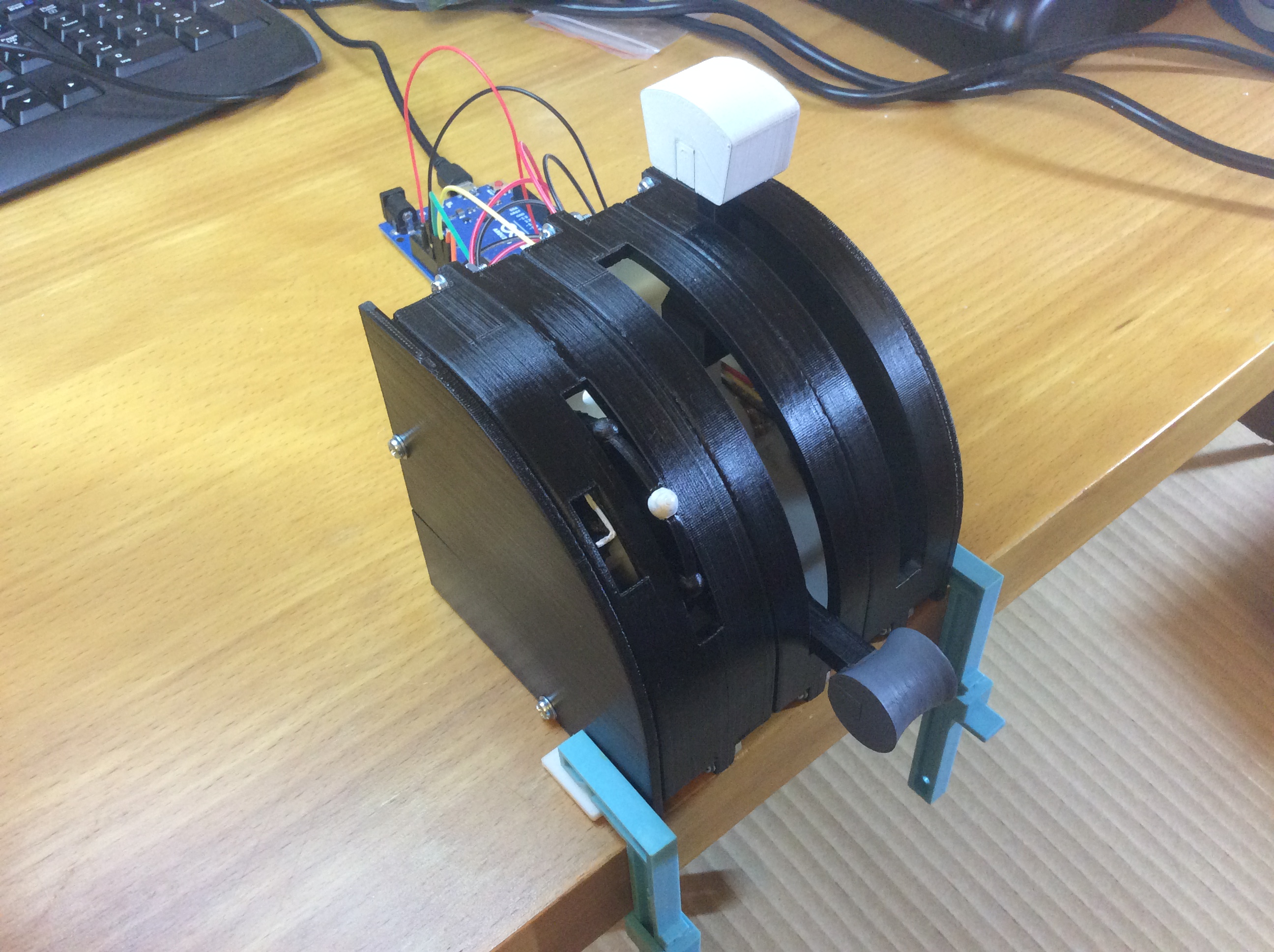
The trim wheel was the most challenging to design and it took several sketched ideas over many days to come up with a design that I thought would provide the look and feel that I wanted.
USB Joystick Interface (HID)
To create a plug-and-play device, the project leverages the HID (Human Interface Device) capability of Arduino. You must use an ATmega32U4-based board like an Arduino Micro or Leonardo. A standard Uno will not work for this purpose.
- The Library: The project uses the official
Joystick.hlibrary by Matthew Heironimus. - The Setup: The Arduino is configured to appear to the computer as a "Flight Controller" with axes like
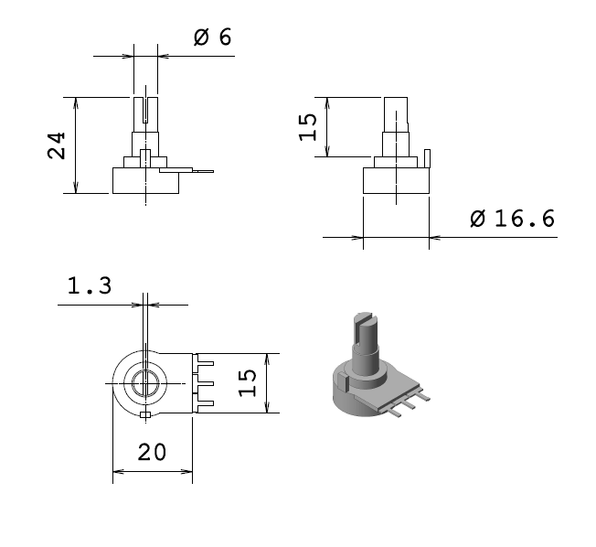
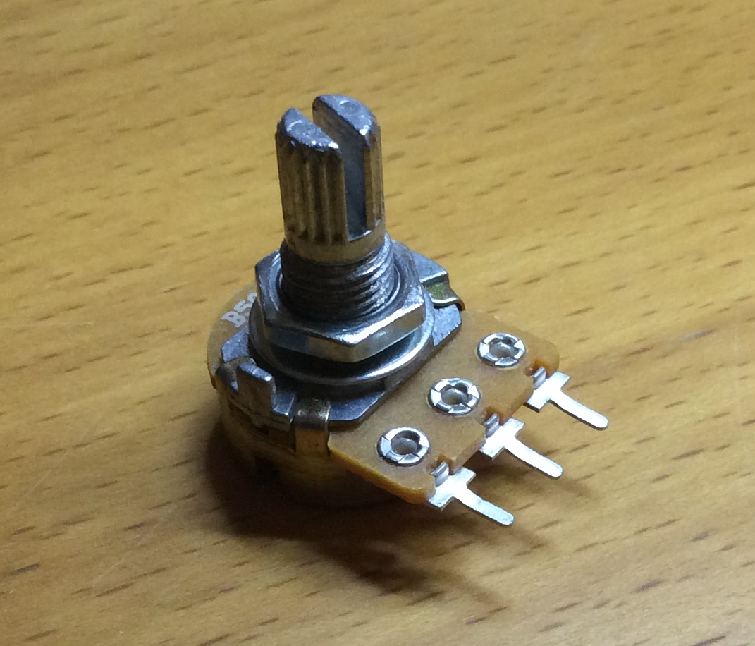
X-Axis,Y-Axis,Z-Axis,Throttle,Rudder, and support for up to 32 buttons. - The Flight Axes: For the throttle and flap levers, the design uses potentiometers. The code reads the analog value (e.g.,
analogRead(A0)), maps it from the 0-1023 range to a suitable output range, and sends it directly to the PC using a command likeJoystick.setThrottle(mapped_value);.
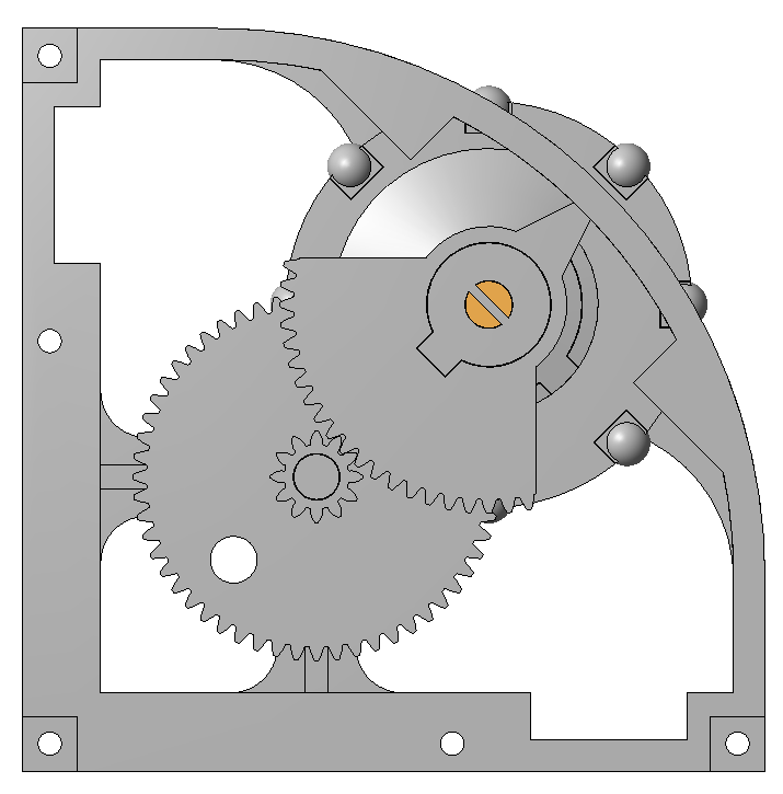
The Trim Wheel Encoders
The elevator trim wheel requires continuous, precise rotation. This is an ideal application for a Rotary Encoder. The Arduino firmware tracks the exact number of "clicks" the wheel is turned, incrementing or decrementing an internal variable. This value is then sent to the flight simulator, allowing for hyper-precise pitch trim adjustment of your virtual aircraft.
Build
All the parts were 3D printed in ABS on my UP! printer, they were then painted and wired up to an Arduino, a Leonardo to start with then swapped over to a Micro. To end up with a plug and play unit which can be stored away easily when not in use.
Parts
Required Hardware:
- Arduino Micro / Leonardo (ATmega32U4): The core HID device.
- Potentiometers: Used for the throttle, flap, and other lever axes, as shown in the images above.
- Rotary Encoder: For the trim wheel.
- Buttons / Toggle Switches: For functions like landing gear, flaps, and lights.
- 3D Printed Enclosure & Components.
3D Printed Part List
Each lever module will require
- 1 x Body left
- 1 x Body right
- 1 x Lever with x detents, 5 variants available with 2-6 detents
- 1 x Lever end
- 1 x Knob, 6 variants available
- 1 x Friction plate, 3 variants available
- 1 x Potentiometer holder
Each wheel module will require
- 1 x Trim wheel body left
- 1 x Trim wheel body right
- 1 x Trim wheel gear
- 1 x Trim wheel hub
- 1 x Trim wheel wheel, if making the assembled wheel
- 8 x Trim wheel nodules, if making the assembled wheel
- 1 x Trim wheel single piece, if making the single piece wheel
- 1 x Trim wheel quadrant
- 1 x Trim wheel quadrant drive
- 1 x Potentiometer holder
Back box parts can be used to house the Arduino and wiring.
Conclusion
A very enjoyable build, very easy from a coding point of view, the real challenge in this build was the design, especially the trim wheel and getting the feel right.