Introduction
I wanted to do a project that uses more LEDs than the Arduino has pins, this involves using shift registers to control the lights and a game is an ideal way of learning how to wire and code such a system. I chose tic-tac-toe as it has straightforward gameplay and can be shown as lights and controlled by buttons. The lights out game is also included as the game board is the same as tic-tac-toe and it just requires extra coding to allow the player to play either game.
Project Overview
The "Dual-Logic Hub" is a masterful example of Hardware Optimization. In embedded systems, GPIO (General Purpose Input/Output) pins are a finite resource. This project demonstrates two critical engineering techniques to bypass these limits: Serialized Output Expansion via shift registers and Analog Multiplexing for tactile inputs. The result is a fully functional console containing 18 LED states and 9 buttons, all controlled using just 4 Arduino pins.
Wiring
There are two distinct circuits in this project, the button circuit and the LED circuit.
Technical Deep-Dive
- The 74HC595 Serialization Forensics:
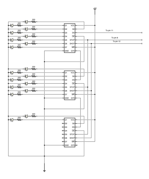
- Bit-Shifting Logic: To control 9 dual-color LEDs (18 individual anodes), the system utilizes three cascaded 74HC595 shift registers. The Arduino sends an 8-bit data packet via the
shiftOut()function. As the "Clock" pin pulses, bits are pushed sequentially into the registers. Once the 24-bit frame (3 registers) is full, the "Latch" pin is toggled, instantly updating the entire physical LED matrix. - SPI-Like Communication: This setup mimics the Serial Peripheral Interface (SPI), allowing high-speed visual updates (flashing winning lines, victory animations) with minimal CPU overhead.
- Bit-Shifting Logic: To control 9 dual-color LEDs (18 individual anodes), the system utilizes three cascaded 74HC595 shift registers. The Arduino sends an 8-bit data packet via the
- Analog Keypad Ladder (The 1-Pin Matrix):
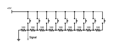
- Voltage Divider Chain: Rather than using 9 digital pins, the project connects all 9 buttons to a single analog pin (A0) via a series of precision resistors. Each button press creates a unique voltage divider circuit.
- ADC Quantization: The Arduino's 10-bit Analog-to-Digital Converter (ADC) maps the resulting voltage to a value between 0 and 1023. The firmware calculates the "Mid-points" between these voltages to determine which specific button was actuated, even accounting for slight electrical noise.
When a button is pressed the voltage of the signal line changes depending on the number of resisters the current has passed through, this voltage is detected by the program and the button number is determined. This circuit only uses one analogue Arduino pin. The left most button in the diagram below is button number 0 and will yield the largest voltage, the right most one is button number 8 and will produce the lowest voltage. Connect the signal output to the A0 pin on the Arduino. To set up this system you must enter some voltages into the program, more on how to do that later.
The second circuit is the LED circuit, it uses 3 shift registers to control the state of the 9 dual colour LEDs, you can think of them as 18 separate LEDs. This circuit only uses 3 Arduino pins. From the top of the diagram below the LEDs are Red0, Red1, Red2 … Red7, Red8, Green0, Green1 … Green7, Green8.
Engineering & Implementation
- Visual Encoding:
- The dual-color LEDs provide a highly intuitive HMI. Red indicates Player 1/Computer, while Green indicates Player 2/User or the "Menu" selection. By pulse-width modulating (PWM) these pins via the shift registers, the system can even generate a "Mixed" amber state for more complex feedback.
- Mechanical Integrity & Packaging:
- The project features a dual-plate laser-cut chassis. The "Mounting Plate" secures the tactile components, while the secondary plate acts as a base. 25mm standoffs provide the vertical clearance required for the complex jumper-wire architecture on the underside.
- Calibration Routine:
- Because resistor tolerances and cable lengths can alter the analog readings, the project includes a dedicated "Voltage Calibration" sketch. This allows the user to profile their specific hardware and update the
voltages[]array for 100% input accuracy.
- Because resistor tolerances and cable lengths can alter the analog readings, the project includes a dedicated "Voltage Calibration" sketch. This allows the user to profile their specific hardware and update the
Instructions
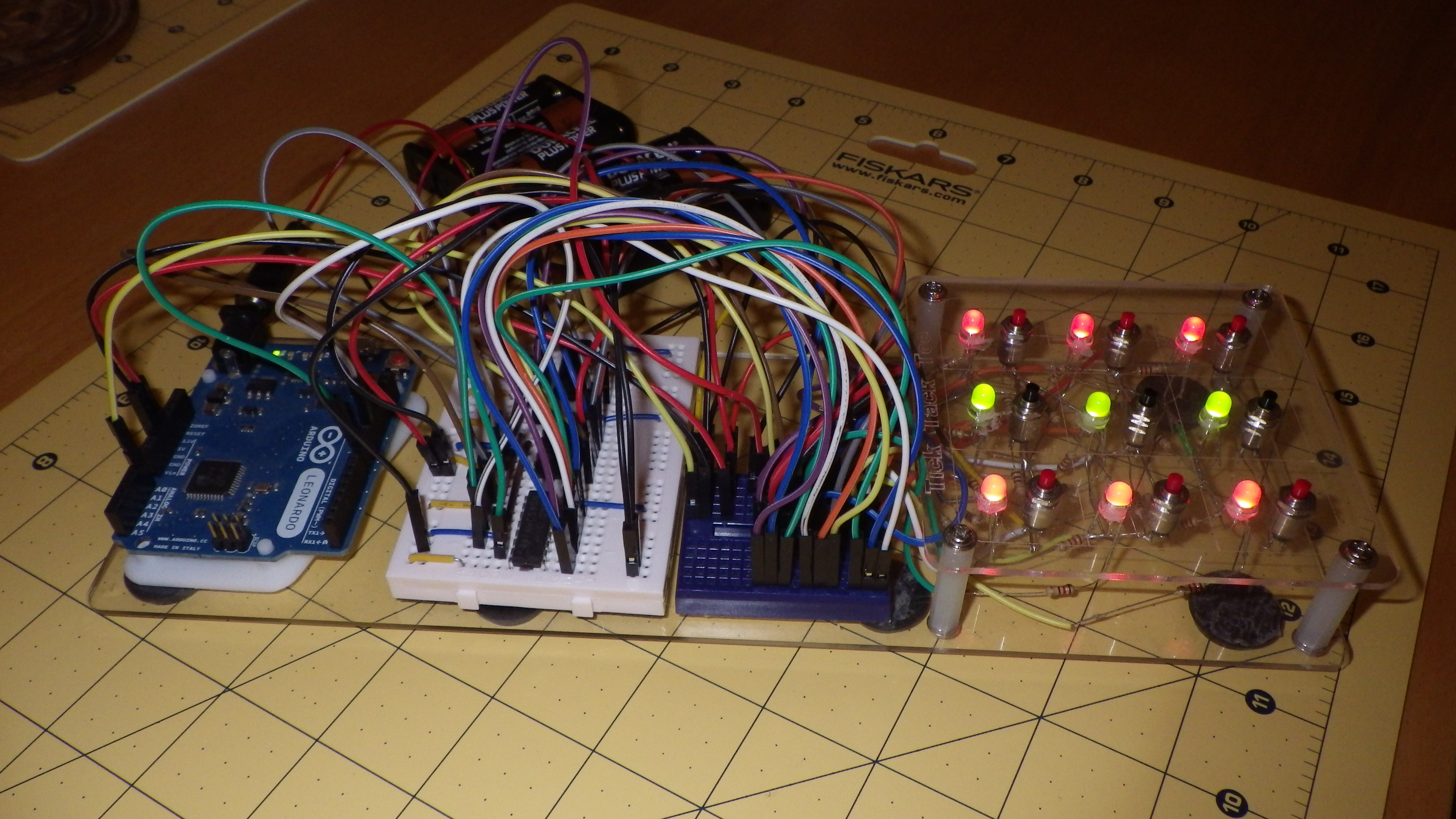
Cut out the 2 plates (dxf files included) and fix the button switches and LEDs into the Mounting Plate. Wire them up as in the diagrams. I know this is much more fiddly work than that simple sentence suggests! If you start with the switches then you can test that before wiring up the LEDs. I fed all the wires out and plugged them into my second breadboard, this allowed a bit more space to then connect them up to the shift registers using another set of jumpers.
To set up the voltages, connect the buttons up as in these instructions and run the buttons program on the Arduino. When the serial monitor is open, if you push a button the voltage displayed is the one to enter into the voltages array in the main program, this array is processed and the mid points between these voltages are used later in the code to determine the button that has been pushed.
Once all the wiring is done and tested, fix the 2 boards together using the PCB stand offs. Put some feet on the bottom to make it more secure when playing and plug in a suitable power source.
Gameplay
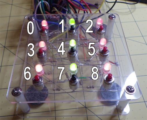
The first arrangement of lights is the menu, it has a column of green lights between the two columns of red. Press a red light to play Tic Tac Toe or a green light to play Lights Out.
Game State Algorithms:
- Tic-Tac-Toe AI: The code maintains a 9-element array representing the board state. After each user move, the MCU executes a move-validation routine and dispatches a counter-move, checking for winning "Triplets" using a bit-masking or conditional logic approach.
- Lights-Out (Cellular Automata): This mode uses "XOR" toggle logic. Pressing a node inverts its state and the states of its adjacent neighbors (North, South, East, West). The game is solved when the sum of the LED array equals zero.
If you choose Tic Tac Toe then you go first and always play red. Press a button to play in that position, the computer will play a move straight after you. If either of you win then the winning line will flash and you will go back to the menu.
If you choose to play lights out then a random pattern of lights is set, your job is to turn them all off again, press any lit light to switch that light and some around it. When you succeed in turning them all off there is a victory display of flashing lights before you are returned to the menu again.
Conclusion
A fun project that taught me all about shift registers and controlling more than you would think from an Arduino, just 4 pins are used for all of the inputs and outputs in these games.
Dual-Logic Hub is an essential project for intermediate makers looking to transition from "One-Pin, One-Component" designs to complex **Serialized Architectures**. It proves that with clever circuit forensics, a simple Arduino Uno can power a multi-game entertainment system with a professional, polished HMI.