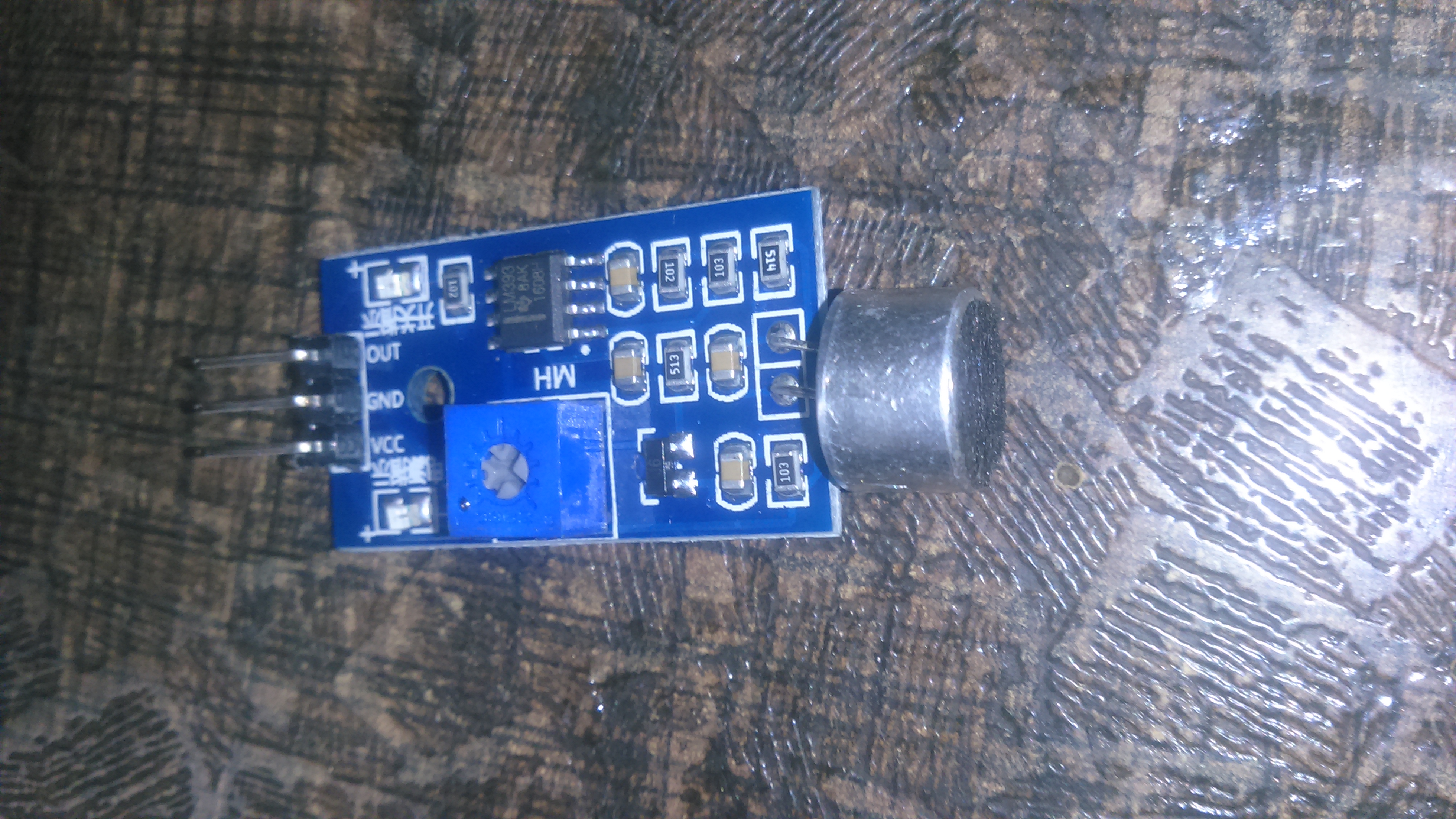
The sound sensor can detect the sound strength of the environment. The main component of the module is a simple microphone and LM393 level convertor chip. The sensor can provide both digital as well as analog output.
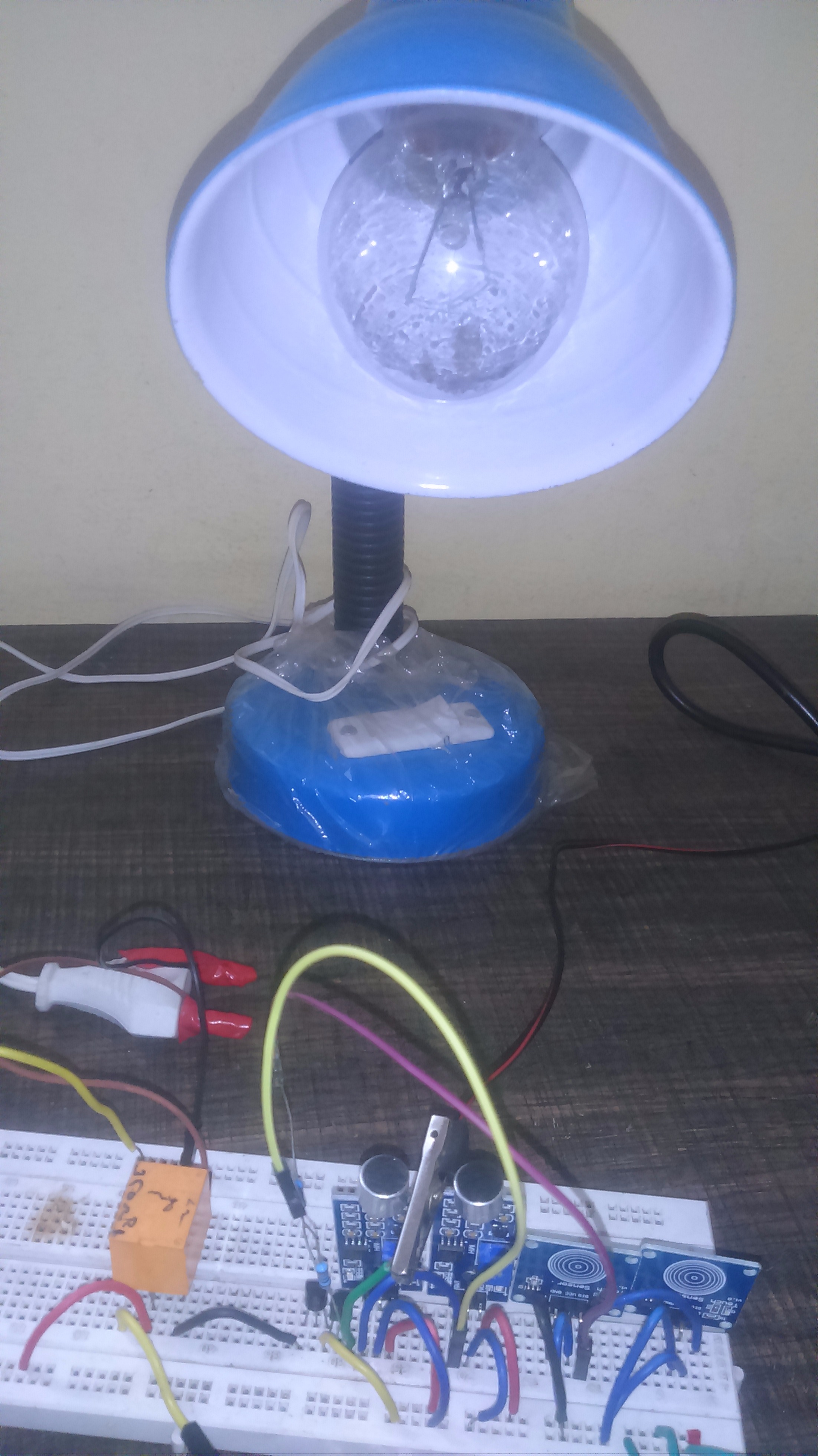
This is my first project and it is working based on two basic sensors—one is a touch sensor and the other one is a sound sensor. When you press the touch pad on the touch sensor, the AC light will switch on. If you release it, the light will be off. The same goes for the sound sensor, which is also used to detect sound. For example, if you clap or make a sound, the DC LED will go on. If no sound, the LED will be off.
Step 1: Main Items
1. AC 230V Operate Light - 1
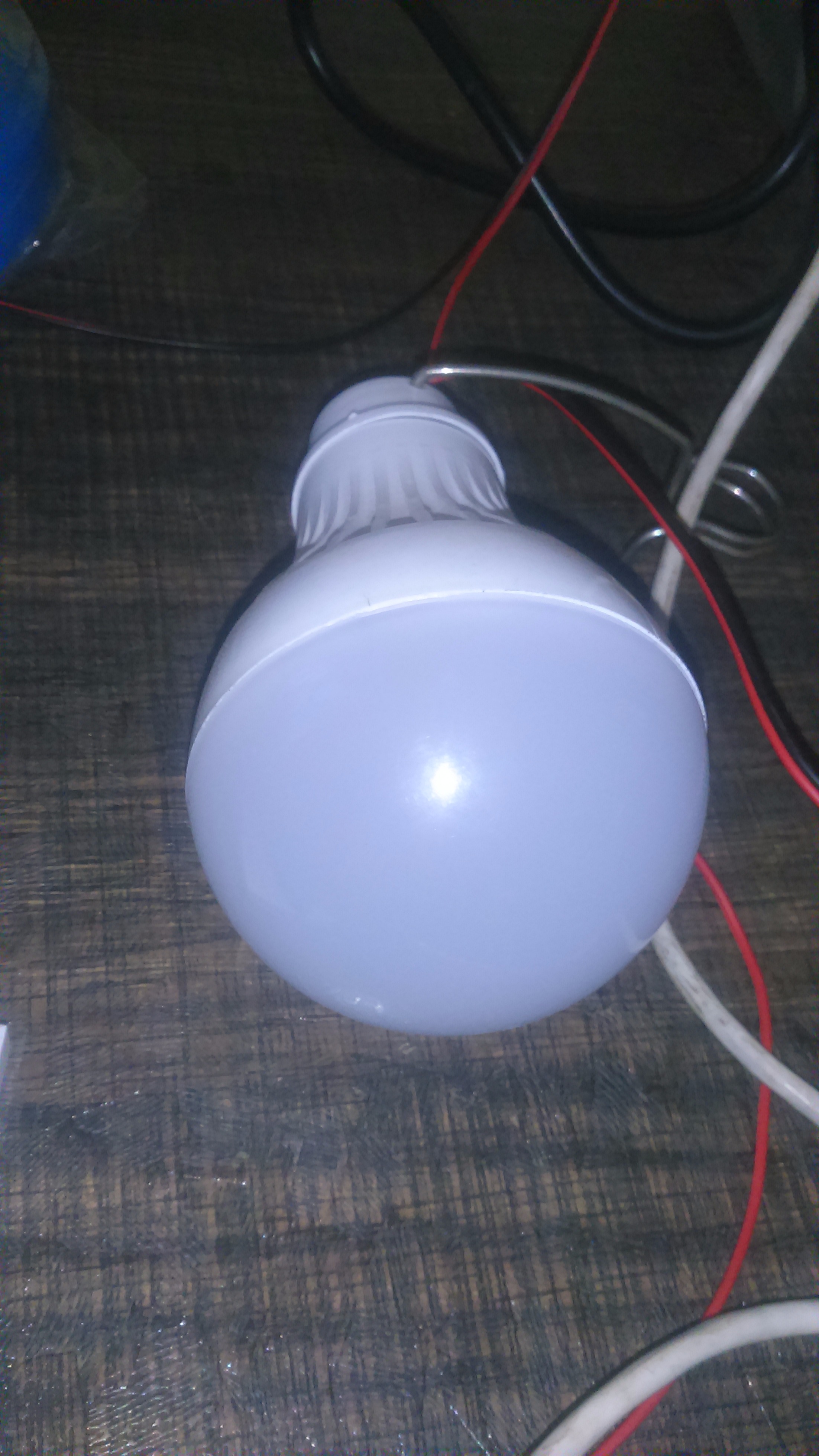
2. DC 12V LED - 1
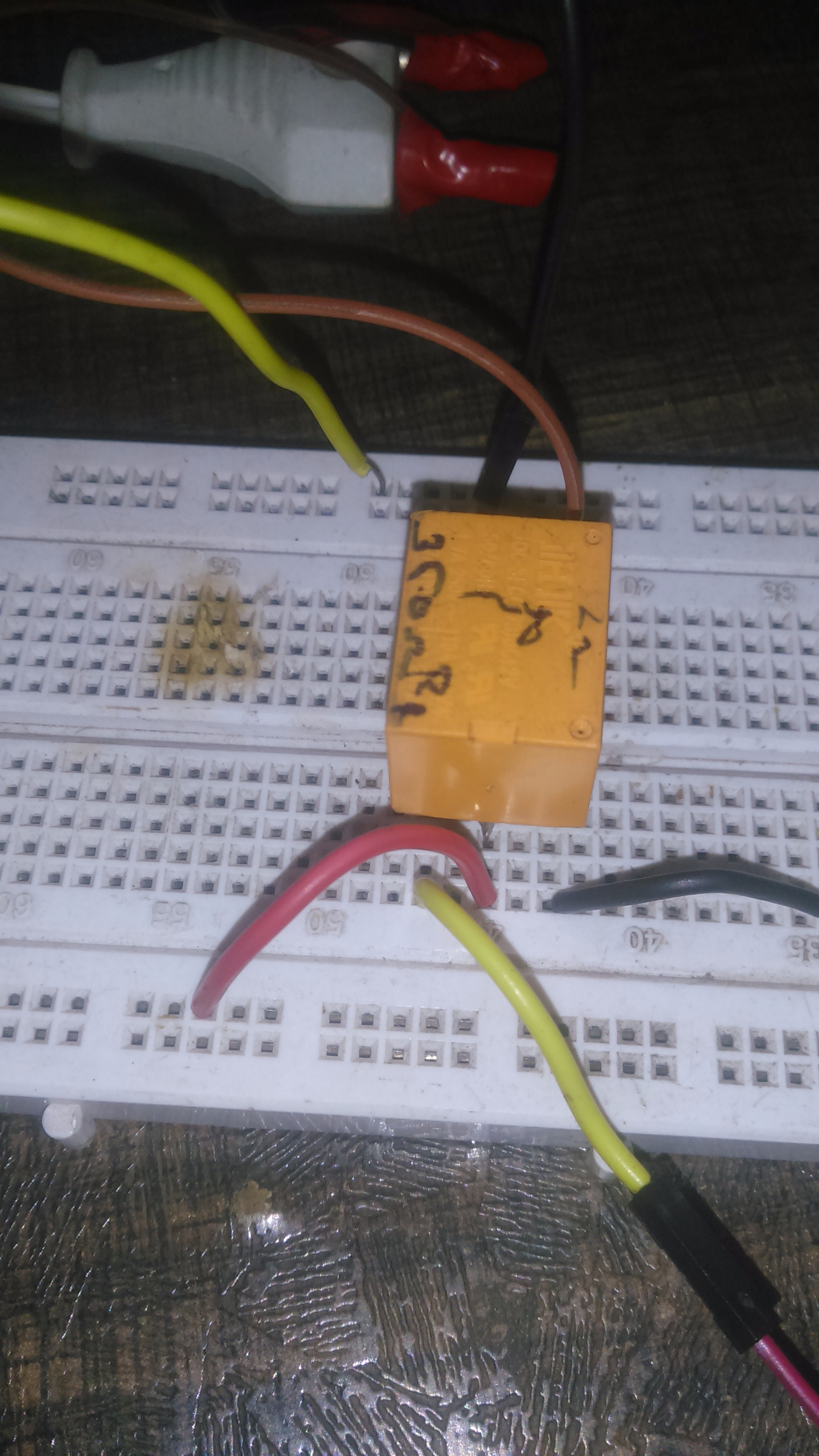
3. 12V Relay - 1
4. NPN Transistor 2N4401 - 2
5. Breadboard - 1
6. Resistor 1K-1/4W - 2
7. Connecting Wires
(Note: Here I'm using Arduino for the only purpose of 5V DC supply.)
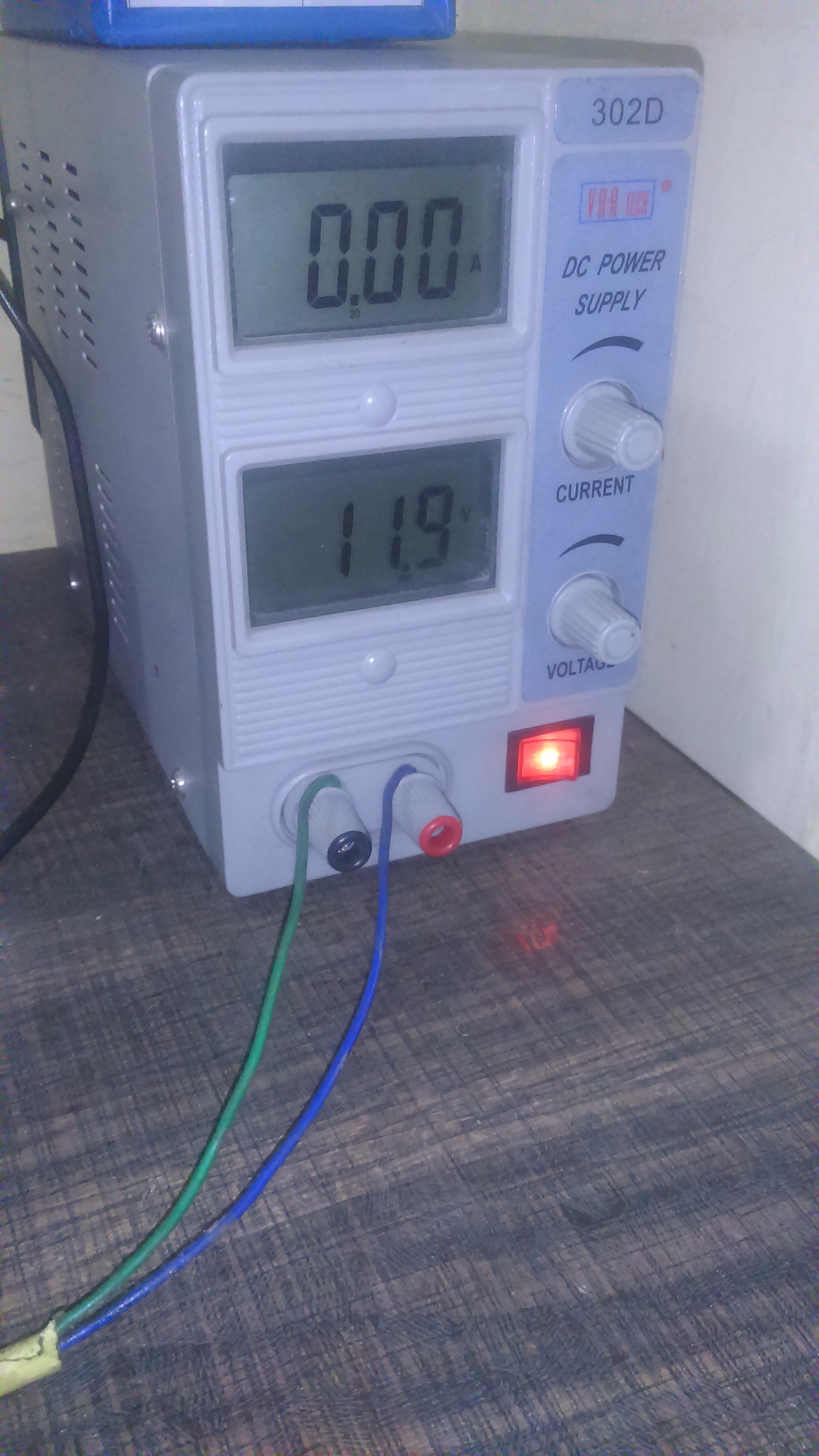
Step 2: AC/DC Power Supply
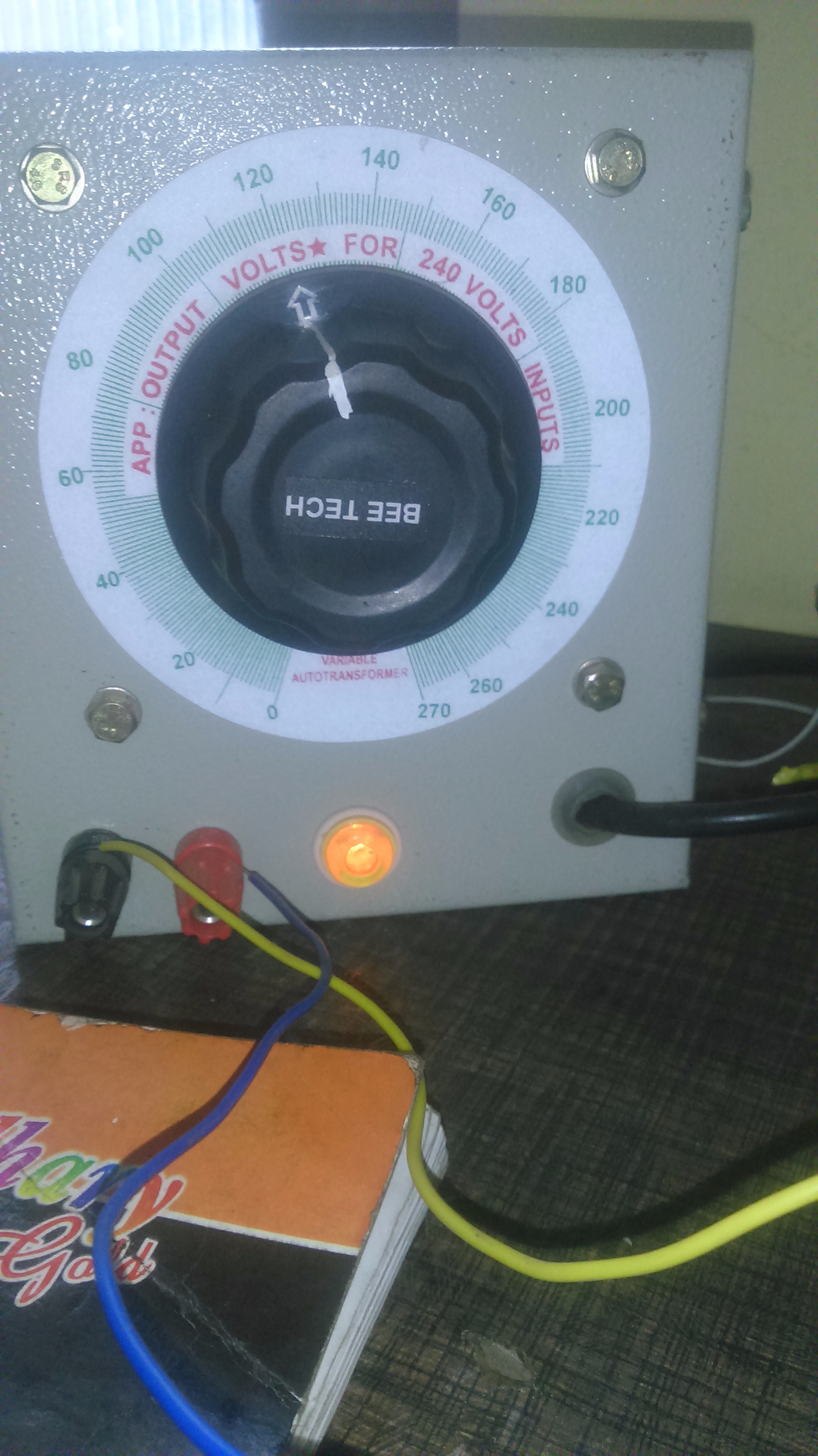
1. AC Power Supply for 270V max. range
2. DC Power Supply for 30V max. range
Step 3: Circuit Diagram
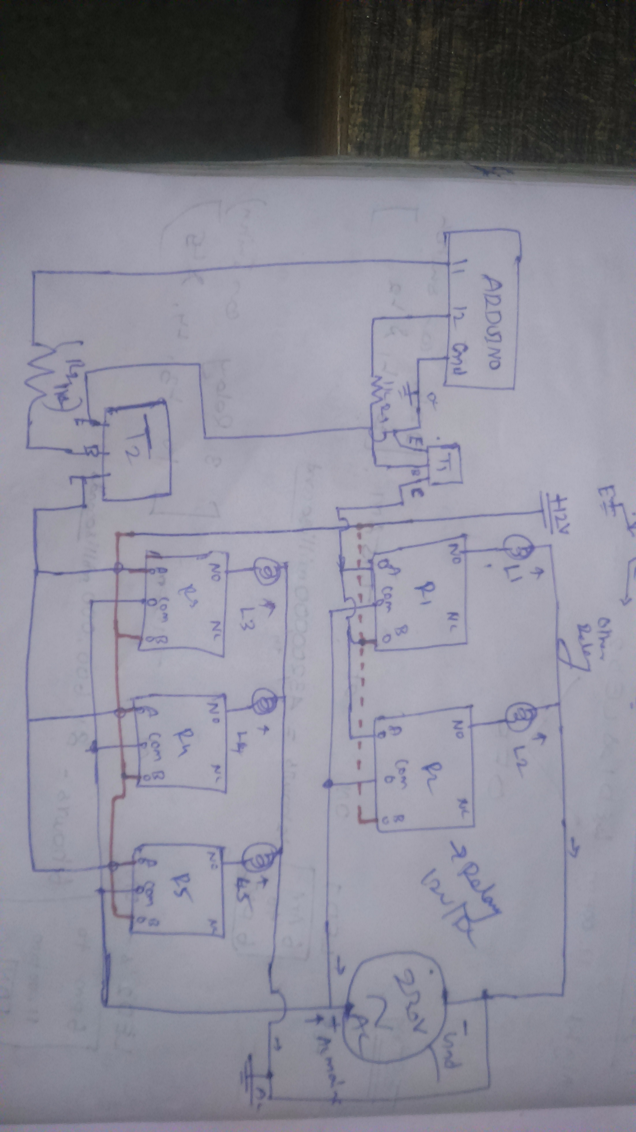

1. Main circuit for 5 AC light control
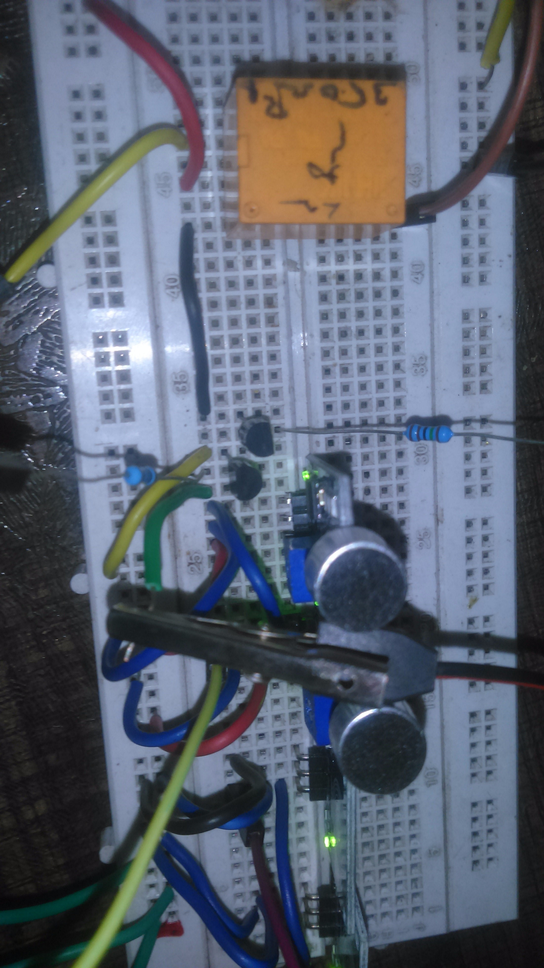
Step 4: Two Sensors with Breadboard Circuit
As per circuit oriented, any doubt email: anbuma343@gmail.com.
Step 5: Video
EXPANDED TECHNICAL DETAILS
Hybrid Home Interactive Lighting
This project combines tactile and acoustic control to manage multiple lighting circuits in a modern smart home.
- Multi-Sensor Input Matrix: Integrates a capacitive TTP223 touch sensor for manual control and an electret microphone module for "Clap" detection. The Arduino manages separate "Strobe" and "Toggle" modes.
- High-Power Relay Isolation: Uses a 4-channel relay module with opto-couplers, allowing the low-voltage Arduino to safely switch 220V AC household lights or 12V DC LED strips.
Responsive Feedback
- LCD Status Monitor: Displays the current "Active Mode" (Touch vs. Sound) and the state of each light on a high-visibility 16x2 I2C LCD.