Control of Speed and Direction of DC Motors by PID Controller and PWM Outputs
Intro
Almost on all available projects, originators would like to control motor speeds and direction together, but they prefer mainly directly sending PWM to DC motors, even via a motor control circuit. But such a method always fails if you need to match speed exactly as you desired because of twin brothers called as “friction” and “inertia”.
(Please never blame to Twins. Whatever and whenever you would like to take some actions with or without something, Twins immediately come and take action just to help you to keep everything under control. While Inertia lets things to “think” before taking action, Friction limits their acceleration and speed. And "power" is "nothing" if it's not under full control.)
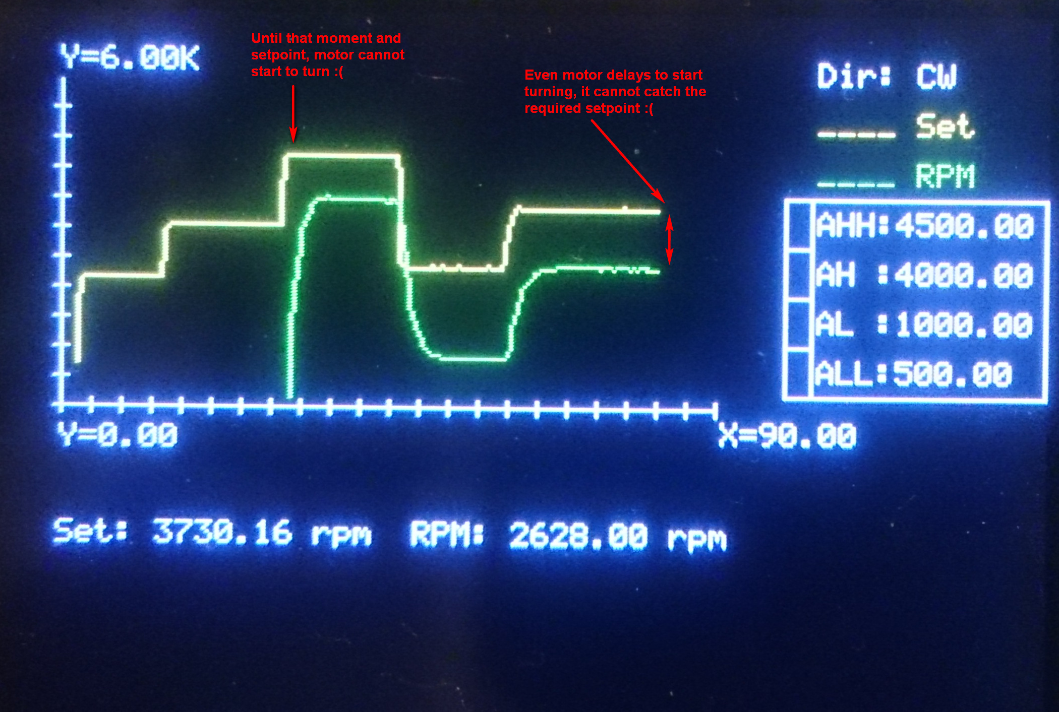
So, if you try to control speed of a motor directly by sending your input as PWM signal to output, actual speed shall never meet with your set point and there will be significant difference (error), as can be seen on the image above. Here we need another way, and it’s called as “PID control”.
PID Controller
What’s PID control? Imagine how to drive your car: To start moving from full stop, you have to depress gas pedal more than during normal cruise. During moving at (almost) constant speed, you don’t need to depress gas pedal too much, but you just recover the loss of speed when needed. Besides, you release it slightly if acceleration is higher than your needs. This is also the way of "efficient driving".
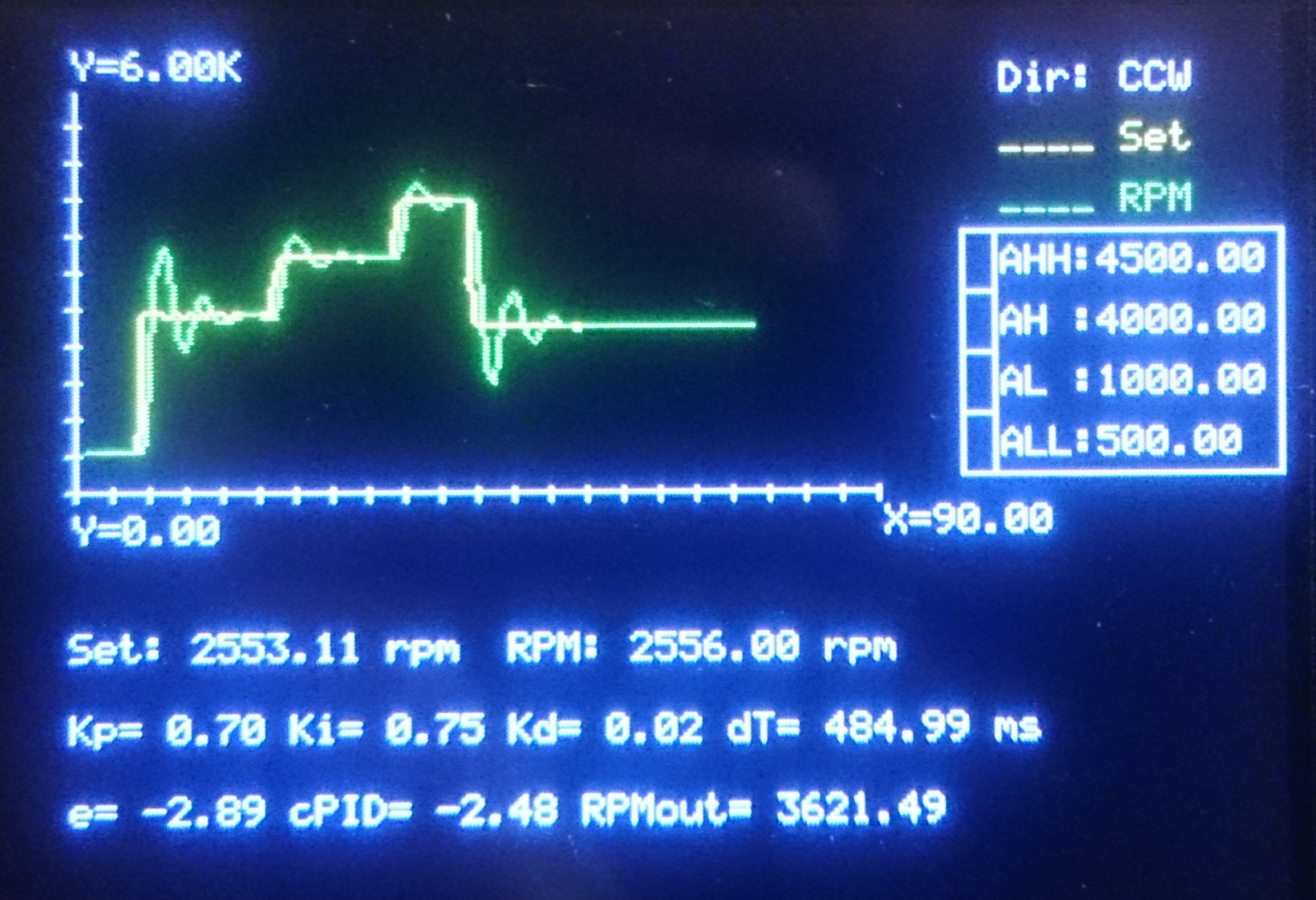
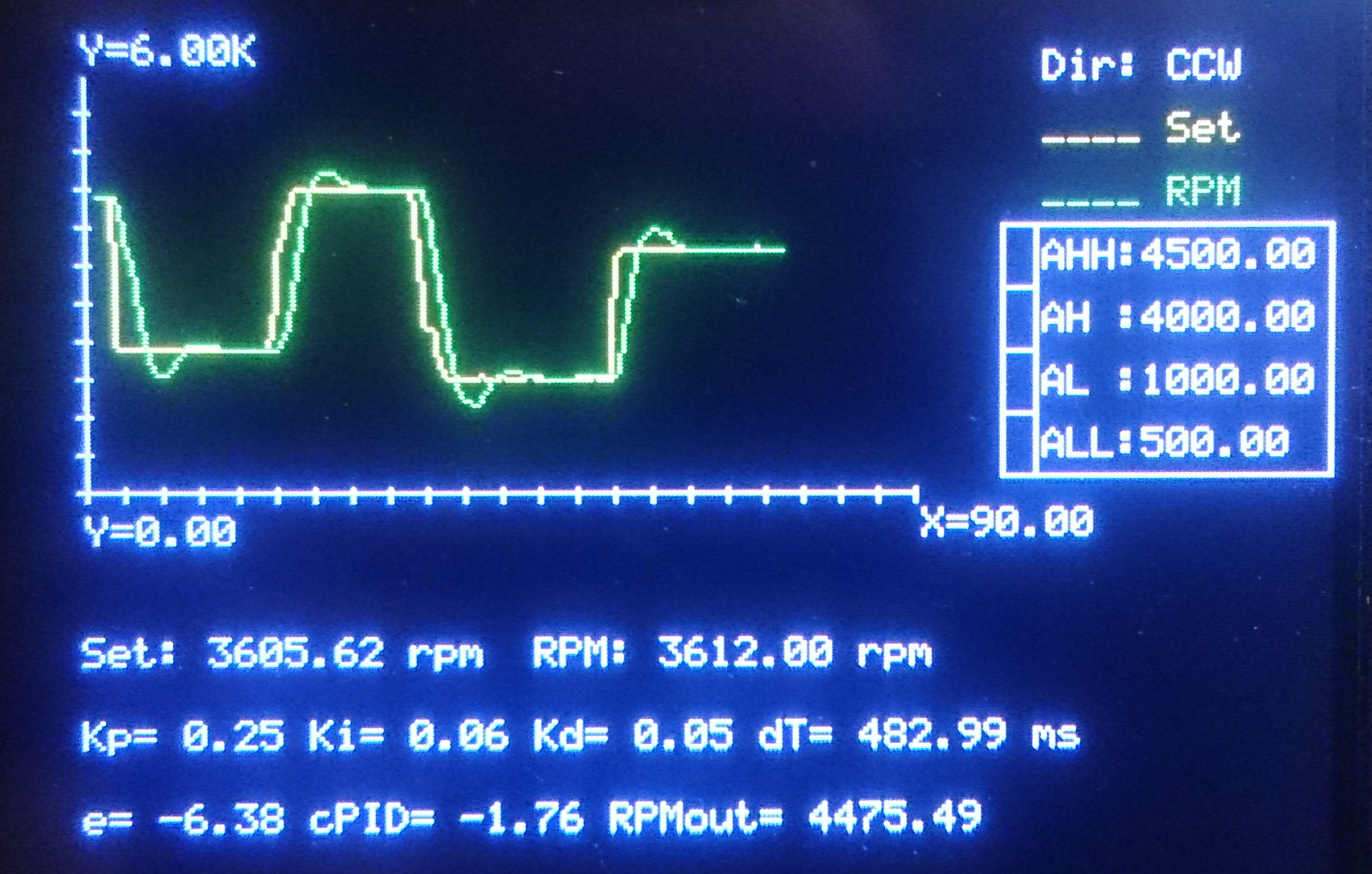
So, PID controller does exactly the same: Controller reads difference “Error Signal (e)” between set point and actual output. It has 3 different components called as “Proportional”, “Integral” and “Derivative”; so controller’s name comes up after first letter of each one. Proportional component simply defines slope (acceleration) of controller output with respect to actual error signal. Integral part sums error signals in time in order to minimize final error. And Derivative component watches out the acceleration of error signal, and puts an “adjustment”. I will not give here further and longer details, please search on internet for further if you interest.
On my Arduino program, PID controller is written as a function shown below:
float controllerPID(float _E,  float _Eprev, float _dT,
                    float _Kp, float _Ki,    float _Kd)
{
  float P, I, D;
  /*
  Base Formula:
  U = _Kp * ( _E + 0.5*(1/_Ki)*(_E+_Eprev)*_dT + _Kd*(_E-_Eprev)/_dT );
  */
  P = _Kp * _E; /* Proportional Component */
  I = _Kp * 0.5 * _Ki * (_E+_Eprev) * _dT; /* Integral Component */
  D = _Kp * _Kd * (_E-_Eprev) / _dT; /* Derivative Component */
  return (P+I+D);
}
Then final output value is determined simply by adding current output value and output of PID controller. It’s the following section of main program together with calculation of Error Signal and PID Controller Output:
/* Error Signal, PID Controller Output and
   Final Output (PWM) to Motor */
E = RPMset - RPM;
float cPID = controllerPID(E, Eprev, dT, Kp, Ki, Kd);
if ( RPMset == 0 ) OutputRPM = 0;
else OutputRPM = OutputRPM + cPID;
if ( OutputRPM < _minRPM ) OutputRPM = _minRPM;
DC Motor Supply Circuit
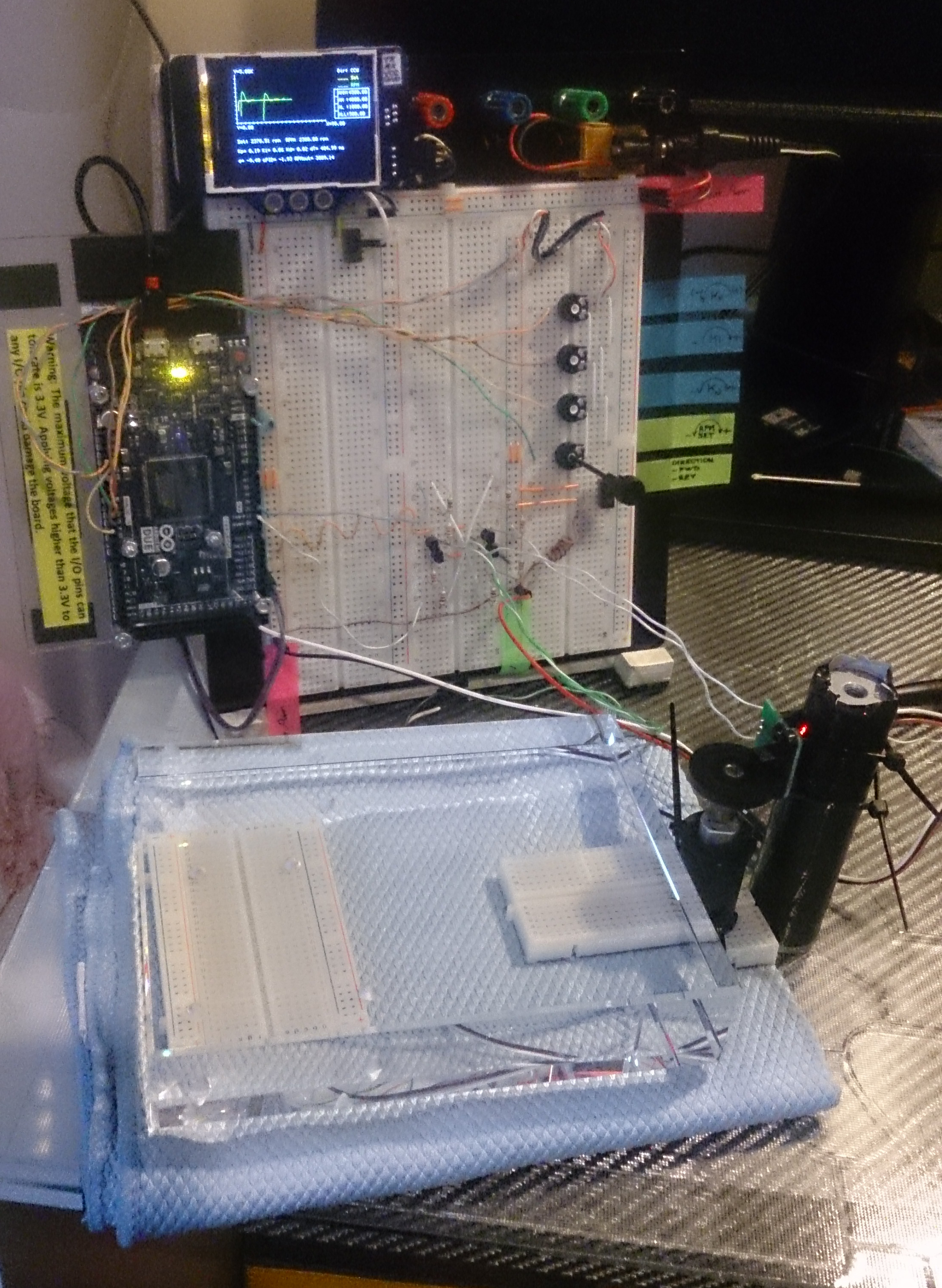
Of course it’s never recommended to drive a DC motor directly from output of Arduino or similar control board. DC motors need significant amount of current comparing to those cannot be supplied by outputs of controller cards. So you need to drive relay coils. But here another problem comes up: Relays have mechanical parts and they can fail in mid- or long term. We need another component here, transistors.
Actually DC motors are driven by current, not by voltage. So by using this principle, I decided to use transistors. But you have to pick up the correct transistor able to withstand motor current. At first, run motor directly by connecting to power supply, and measure current at the maximum operating conditions, or refer to manufacturer specifications.
After doing this, I decided to use four BC307A PNP bipolar junction transistors on a “bridge” to determine direction of current through motor coils (actually an NPN BC337 set would work better due to ability of withstanding significantly higher collector currents, but I didn't have them at the time).
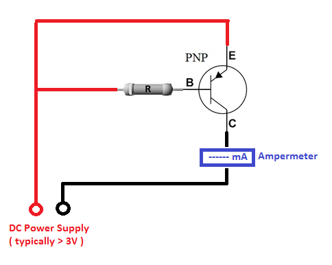
Since motor currents should be passed through Emitter-Collector path of transistor, it’s necessary to use transistors with approximately same DC Current Gain (hfe) coefficients. To check it out, you can use following circuit, and collect transistors giving you approximately the same current reading on ampermeter. To design those preliminary circuits, you have consider followings:
- Find “Base-Emitter On-Voltage” (VBEon) of transistor. It’s the minimum voltage to be applied to Base for switching transistor on.
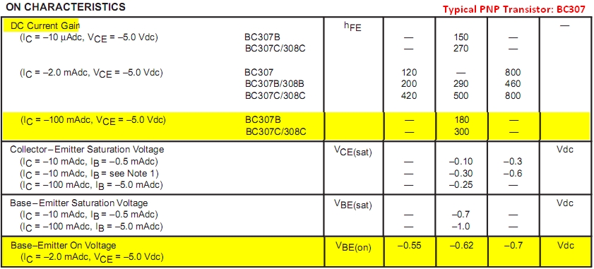
- Find typical “DC Current Gain” (hfe) of transistor at around the Collector Current close to Motor Current. Typically it’s the ratio between Collector Current (IC) and Base Current (IB), hfe = IC / IB.
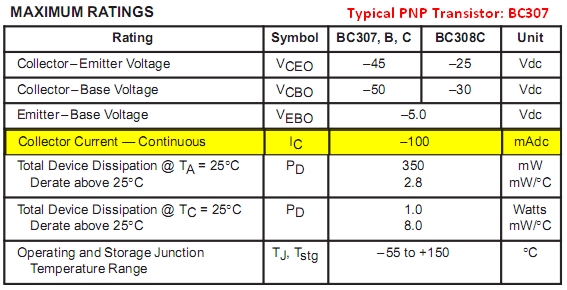
- Find “Maximum Continuous Collector Current” of transistors (ICmax). The DC current of motor should never exceed this value in terms of absolute values. I can use BC307 since the motor I use needs on 70 mA while transistor has ICmax(abs) = 100 mA.
Now you can determine the resistor value to be connected to Base: At first, you have to consider limitations of your controller card's output, and try to keep Base current as minimum as possible (so it's recommended to select transistors' DC Current Gain as maximum as possible. Take the voltage rating of output on controller board as “Trigger Voltage” (VT), and find the Required Base Current (IBreq) by dividing Motor Current (IM) to DC Current Gain (hfe) of transistor: IBreq = IM / hfe.
Then determine the Voltage to be dropped across Resistor (VR), by subtracting Base-Emitter On-Voltage (VBEon) from Trigger Voltage: VR = VT - VBEon.
Finally divide Voltage to be dropped across Resistor (VR) to Required Base Current (IBreq) to find Resistor Value (R): R = VR / IBreq.
[ Combined formulation: R = ( VT - VBEon ) * hfe / IM ]
On my case:
- Motor Current: IM = 70 mA
- BC307A Parameters: ICmax = 100 mA, hfe = 140 (I measured approximately), VBEon = 0.62 V
- Trigger Voltage: VT = 3.3 V (PWM output of Arduino Due)
- R = 5360 ohm (So I decided to use 4900 ohms made by a 2K2 and 2K7, to ensure full RPM range coverage and circuit just sucks ~0.6 mA from PWM output - a suitable design.)
Advanced Motor Control Logic
This project serves as a masterclass in driving inductive loads safely and efficiently using an Arduino.
- The Flyback Diode Trick: A critical component for protecting your circuit is the flyback diode. When a motor is suddenly turned off, its inductive coils generate a high-voltage spike called "Back-EMF." This spike can easily damage the Arduino or the transistors. Placing a diode like a 1N4007 across the motor terminals (cathode to positive, anode to negative) provides a safe path for this current to dissipate, protecting your electronics.
- H-Bridge Mastery: While this project uses a discrete transistor bridge, a common and robust alternative is an integrated H-bridge like the L298N. An H-bridge allows you to control both speed (via PWM) and direction by electronically flipping the current flow through the motor, enabling forward and reverse operation without mechanical switches.
Reverting Direction and Important Notes
To revert direction of a DC motor, it’s enough to revert current flow. To do that, we can simply make a bridge circuit with four transistor sets. On the schematic; PWM Output#2 activates T1A and T1B while PWM Output#3 activates T2A and T2B, so the current passing through motor is changed.
But here we have to consider another issue: When just started, electric motors suck transient start-up current significantly higher than nominal current you read during normal/continuous operation (manufacturers give only nominal currents). Start-up current might be approximately 130% of nominal one for small power motors, and increases depending on motor power. So, if you feed motor directly from a voltage source and immediately reverse polarity during operation, motor sucks extreme levels of current since it’s not fully stopped. Finally this may result blowing out the power source or burning motor coils. This may not be so important and felt for very small power motors, but becomes important if power levels you’re working on increased. But if you're powering up motor through a transistor or a set of transistors (like Darlington Couple), you don't have such a problem since transistors already limit the current.
Anyway, I considered a small routine on program: When direction selection is changed during running, the program drives both command outputs to zero at first, and waits for motor until full stop. Then it finishes its duty, and gives all control back to the main routine.
if ( Direction != prevDirection )
 {
  /* Killing both of the PWM outputs to motor */
  analogWrite(_chMotorCmdCCW,0); analogWrite(_chMotorCmdCW,0);
  /* Wait until motor speed decreases */
  do
   { RPM = 60*(float)readFrequency(_chSpeedRead,4)/_DiscSlots;   }
  while ( RPM > _minRPM );
 }

Software Tricks
- Acceleration Ramping: A simple yet effective software technique is to implement acceleration ramping. Instead of jumping the PWM duty cycle from 0 to the target value instantly, you can write code to increment it gradually over a set period (e.g., from 0 to 255 over 1 second). This prevents the high "inrush current" that occurs when a stationary motor is suddenly powered, which can cause the Arduino to brown-out reset or blow a fuse.
Speed Reading
On my application I used a cheap HC-020K speed sensor. It send pulses at the level of its supply voltage, and datasheet says that supply voltage is 5V. However my board is Arduino Due and it cannot accept it. So I directly powered it from Due’s 3.3V output, and yes, it worked. And following function is written to read frequency and HC-020K output.
int readFrequency(int _DI_FrequencyCounter_Pin, float _ReadingSpeed)
{
 pinMode(_DI_FrequencyCounter_Pin,INPUT);
 byte _DigitalRead, _DigitalRead_Previous = 0;
 unsigned long _Time = 0, _Time_Init;
 float _Frequency = 0;
 if ( (_ReadingSpeed<=0) || (_ReadingSpeed>10) ) return (-1);
    else
      {
        _Time_Init = micros();
        do
         {
          _DigitalRead = digitalRead(_DI_FrequencyCounter_Pin);
          if ( (_DigitalRead_Previous==1) && (_DigitalRead==0) ) _Frequency++;
          _DigitalRead_Previous = _DigitalRead;
          _Time = micros();
         }
        while ( _Time < (_Time_Init + (1000000/_ReadingSpeed)) );
      }
 return (_ReadingSpeed * _Frequency);
}
Note that HC-020K’s wheel has 20 slots, simply read frequency is to be divided by 20 in order to get revolution per second as frequency. Then result should be multiplied by 60 to get RPM.
RPM = 60 * (float)readFrequency(_chSpeedRead,4) / _DiscSlots;
Graphical Touch-Ups
In order display the inputs and results, I used a Makeblock Me TFT LCD and wrote CommandToTFT() function to send commands to it. Actually reason of this function is just to change serial connection point just at a single row in program, when needed.
Cartesian_Setup(), Cartesian_ClearPlotAreas() and Cartesian_Line() functions are written to prepare graphic plotting area, clear plot area when reached to the end of horizontal axis (here it’s “time”) and plot graphics respectively. Refer to Makeblock Me TFT LCD manual for further details if you interest graphical functions here, because I will not explain them here since they're actually out of this blog's scope.
Ending
Here I copy the program with- and without graphical functions separately, so you can review Speed and Direction Control Implementation standalone, or with graphics. Besides, on the Codes you can find further explanations for programmed functions.
Finally, normally you cannot decrease speed of a DC motor below 10-20% of its rated speed, even there's no any load. However, it's possible to decrease down to nearly 5% by using PID-control for an unloaded DC-motor once it's started.
Edit (25.Feb.2018): If you would like to use NPN transistors instead of PNP, you have to consider also reverse current flow on both types. When triggered (switched on) current flows from Emitter to Collector on PNP transistors, but it's reverse for NPN types (from Collector to Emitter). Hence PNP transistors are polarized as E(+) C(-) and for NPN it should be C(+) E(-).