Silicon Technolabs: Digital & Analog IO Breakout Board
Project Perspective
This Digital & Analog Breakout Board is a fundamental layout for anyone just starting their journey into electronics and microcontrollers. By focusing on the essential building blocks of any Arduino project—digital and analog inputs and outputs—you'll learn how to interact with the world around you and build a strong foundation for more complex systems. If you are starting to learn ARDUINO or Microcontrollers, this tiny prototype board is very easy to interface with some basic knowledge of electronics. Using this tiny prototype board you can build small projects to bring your development to life.
Technical Implementation: Digital vs. Analog
The project clarifies the distinction between two core types of interaction:
- Digital layer: Digital pins can be in one of two states: HIGH (5V) or LOW (GND). You'll learn how to read buttons (inputs) and blink LEDs (outputs) using these states.
- Analog layer: Analog pins can read a continuous range of voltages, from 0V to 5V, which are converted into a number from 0 to 1023 by the Arduino's ADC (Analog-to-Digital Converter). You'll learn how to use potentiometers and sensors (inputs) and control brightness (outputs) using PWM (Pulse-Width Modulation).
1. Digital & Analog Breakout Board
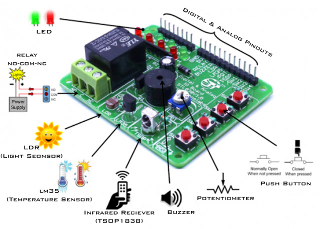
Digital & Analog Breakout Board is a basic peripherals prototype board for ARDUINO and other microcontrollers. If you want to monitor room temperature and switch devices on-off through IR remote control, this board has all the required sensors to start small projects.
2. Feature
Input
- Temperature (Analog): LM35, linear 10 mV/°C Scale Factor, rated for −55°C to 150°C range.
- Light (Analog): 5 mm Light Dependent Resistor.
- Potentiometer (Analog): 10k ohm Sweep Potentiometer.
- Infrared Remote Control Receiver (Digital): TSOP1838 compatible with 38 KHz IR remotes.
- Push Button (Digital): 6 mm tact switch.
Output
- LEDs (Digital): 4-Red, 4 Green Digital outputs.
- Piezo Buzzer (Digital): Multi-tone Buzzer Frequency up to 2 KHz.
- Relay (Digital): 250VAC/7A,125VAC/12A,24VDC/12A.
- Reverse polarity protection.
- 0.1”(2.54mm) Male headers for digital and analog interface pin.
- High quality PCB FR4 Glass epoxy.
- Four 3mm mounting hole for easy mounting.
- Very small footprint so easy to handling.
Specifications
- Power supply: 5v DC.
- Size: (LxBxH) 55 x 68 x 15mm.
- Weight : <100 Gram.
Hardware Infrastructure
- Arduino Uno: The central brain that processes signals and controls the breakout board.
- Digital & Analog Breakout Board: A convenient way to test digital inputs (buttons) and outputs (LEDs, buzzer, relay) and analog inputs (sensors, potentiometer) without messy wiring.
- Micro-USB Cable: Use for initial code uploads and to connect the Arduino to your computer for power and data.
- Jumper Wires: Connect all the components together.
Software Logic & Signal Flow
The Arduino code is designed to be clear and step-by-step:
- Setup: Use
pinMode()to tell the Arduino which pins are inputs and which are outputs. - Read Digital: Use
digitalRead()to check if a button is pressed ('HIGH' or 'LOW'). - Write Digital: Use
digitalWrite()to turn an LED on ('HIGH') or off ('LOW'), or activate the buzzer or relay. - Read Analog: Use
analogRead()to get a value from a sensor like the LM35 or LDR (0-1023). - Write Analog: Use
analogWrite()to dim an LED using PWM (0-255).
Future Expansion
- Custom Sensor Integration: Connect other sensors and see how their signals are read as digital or analog.
- Simple UI Design: Use buttons and potentiometers to create a basic menu system for controlling several outputs.
- Data Visualization Integration: Use the Serial Plotter in the Arduino IDE to visualize analog readings from the temperature or light sensor as a real-time graph on your computer screen.
- Serial Monitor Feedback: Use the
Serial.print()andSerial.println()functions to send digital and analog readings to your computer for easier debugging.
This project is an essential "Hello, World!" for understanding how sensors and actuators communicate with a microcontroller.