The story
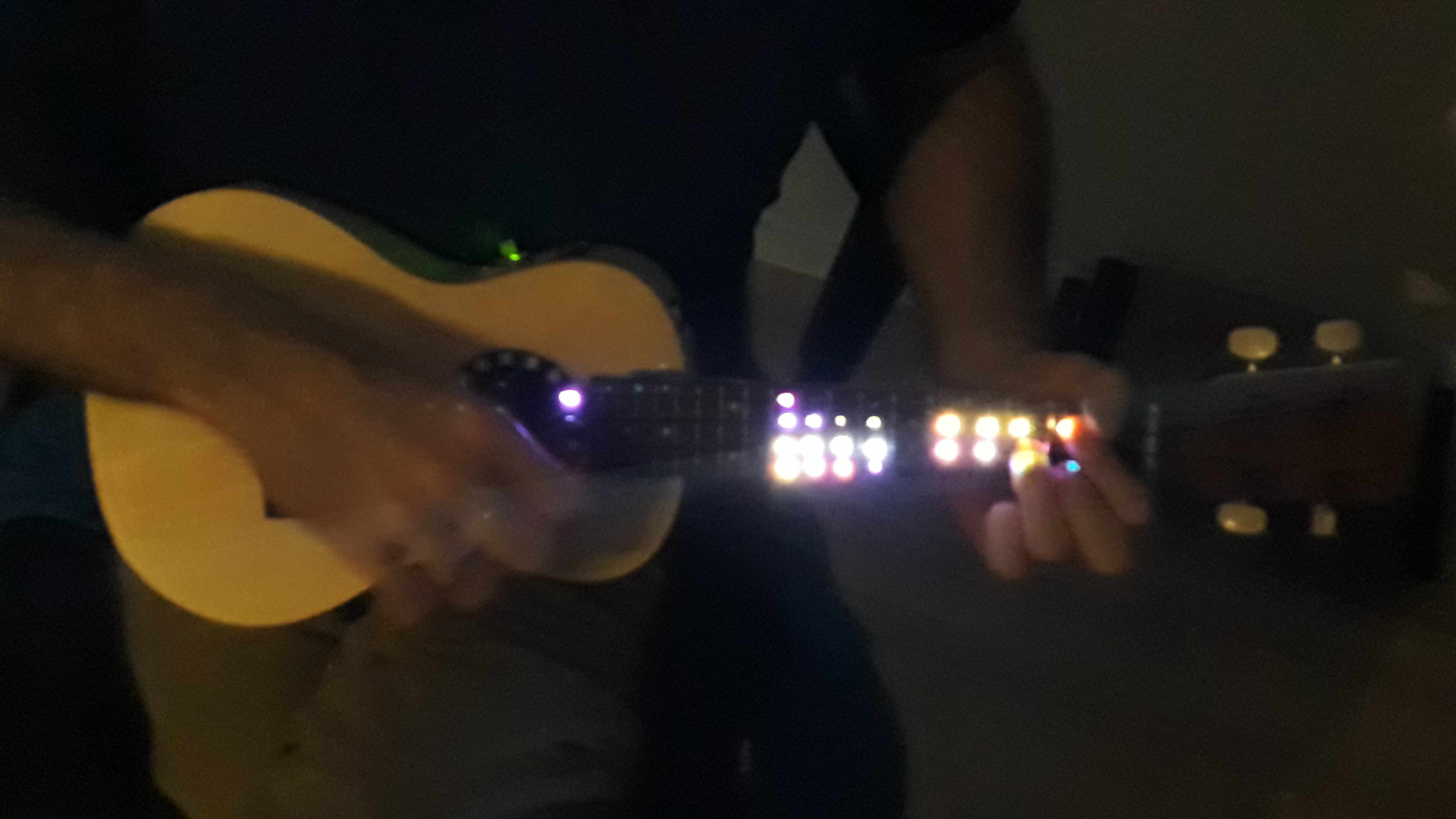
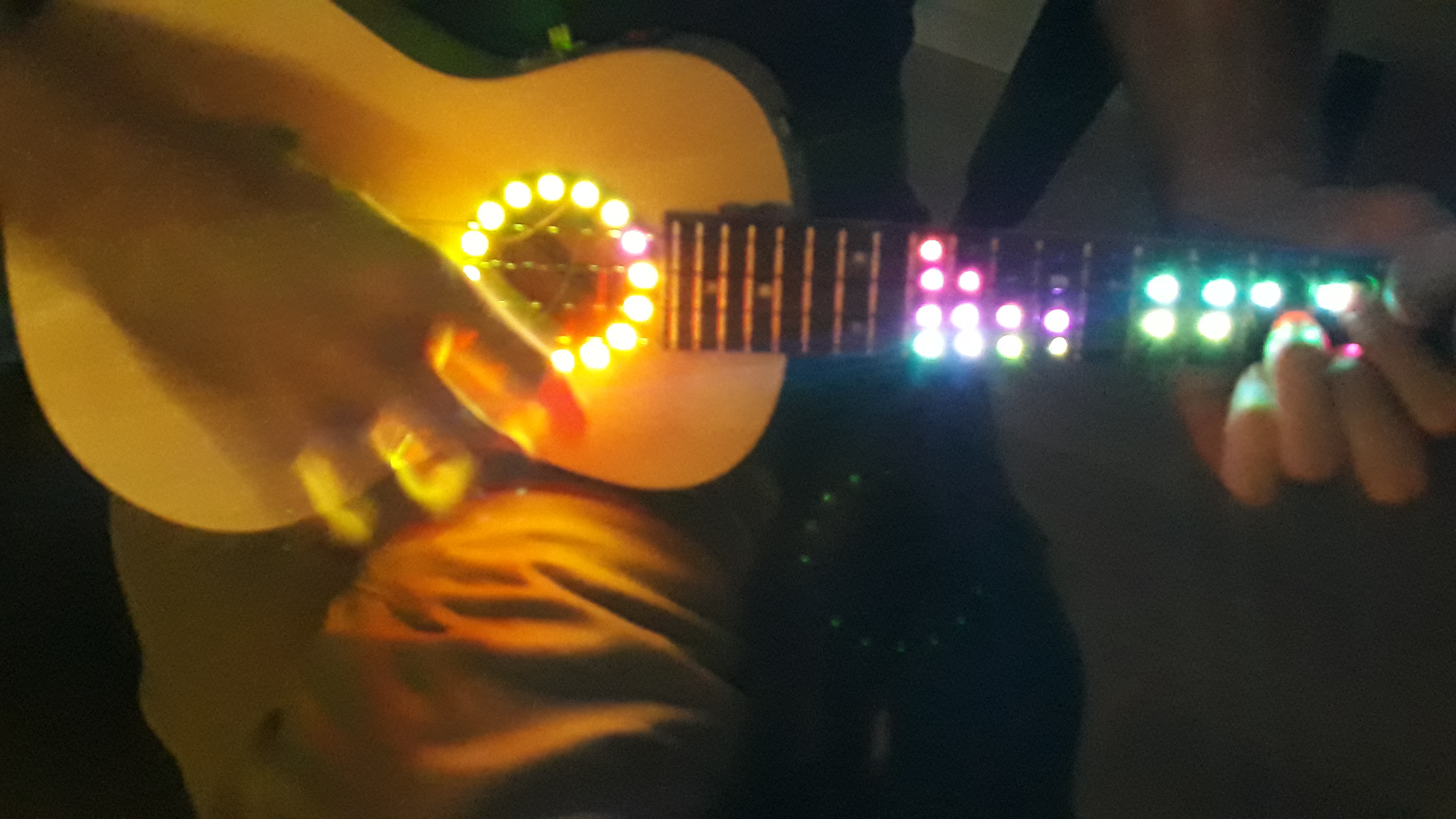
I was wondering how an illuminated music instrument might look like in the dark.
To allow for a certain dependence of the illumination pattern and the instrument's sound, audio spectrum analysis seemed to be a reasonable approach.
As instrument I chose a ukulele since there are DIY (do it yourself) construction kits available at a reasonable price and I had a crude idea of how to get the LEDs in.
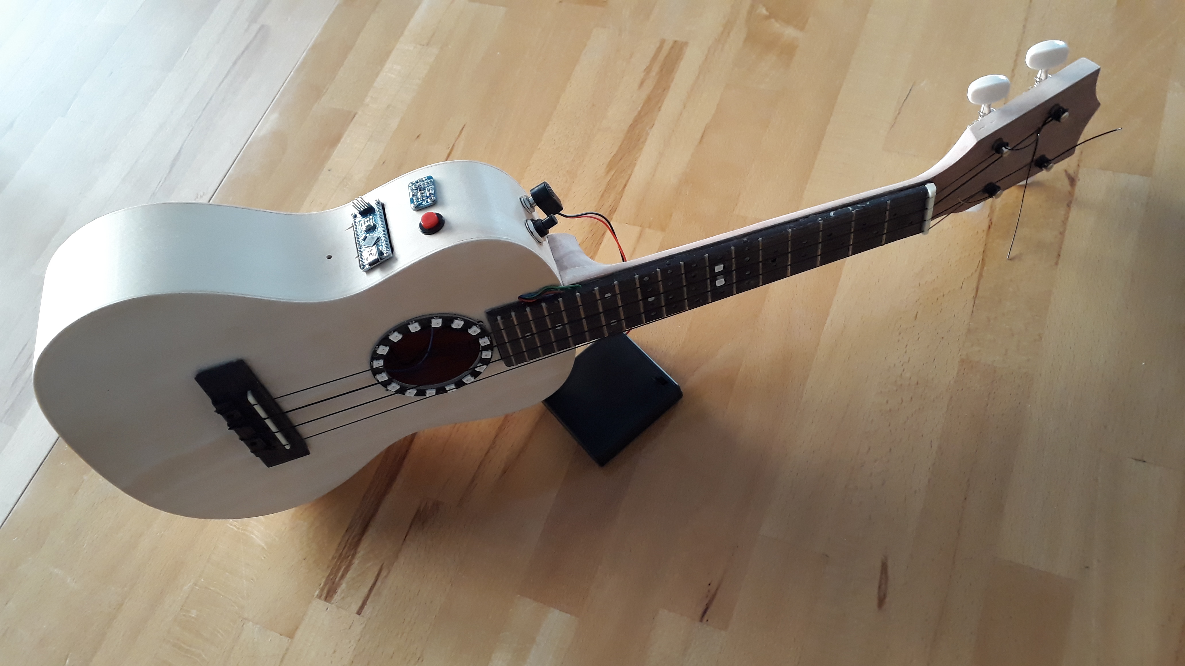
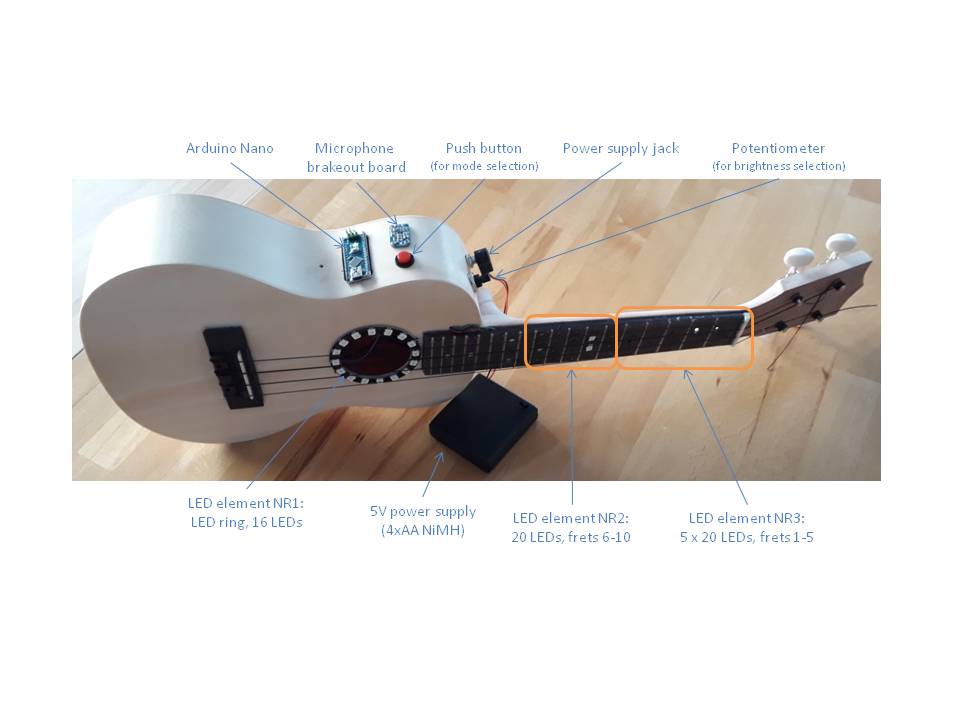
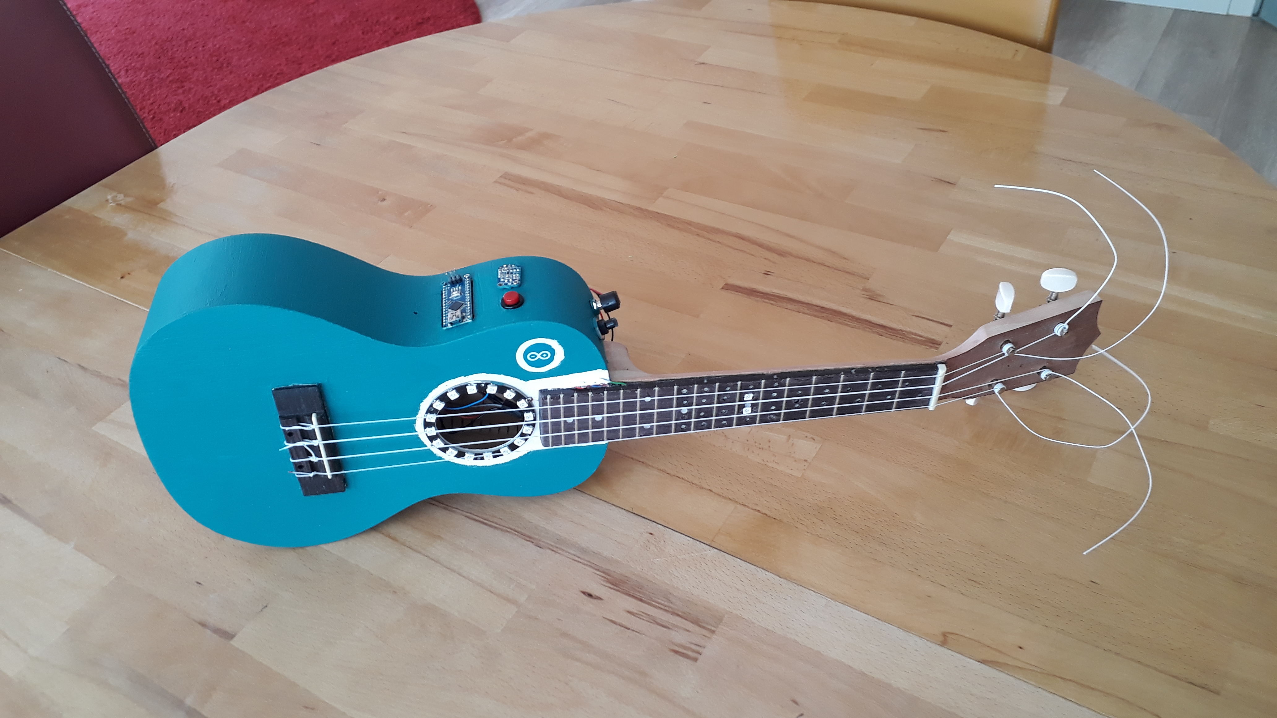
Here a quick glance at the result: A concert ukulele w/ 3 optical elements (2 LED strips in the fretboard, 1 LED ring around the sound hole).
UPDATE 1: Meanwhile I built a 2nd (larger) LED Ukulele and added some burning fire effect, see below.
Ideas for the future:
- Use LEDs do display grip patterns for chords or even simple solo lines based on input from a mobil device wirelessly coupled. Update 2020-07-15: Stumbled across something like this here: https://www.instructables.com/id/LED-Ukulele-Level-One/
Core Technology: Real-Time FFT Spectrum Analysis
The "brain" of the project is an Arduino Nano, which performs Fast Fourier Transform (FFT) analysis on the audio signal captured by an Adafruit MAX4466 Electret Microphone.
- Audio Processing: The microphone captures broad-band acoustic vibrations from within the ukulele's body.
- Frequency Mapping: The FFT algorithm breaks the complex sound wave into its constituent frequency bins (Low, Mid, High). These bins are then mapped to three distinct optical elements.
- Optical Elements:
- Fretboard Strips: Two vertical WS2812B LED strips embedded beneath the strings.
- Sound-Hole Ring: A 16-LED ring surrounding the center of the instrument.
- Total Control: 30 individually addressable LEDs are managed using the FastLED library.
Advanced Luthier Engineering and Electronics
Embedding electronics into a wooden acoustic instrument presents significant manufacturing challenges:
- Modified Fretboard: To accommodate the LED PCBs (~3mm height) without compromising playability, a 2mm layer of foam rubber was inserted between the fretboard and the neck, providing insulation and space for complex wiring.
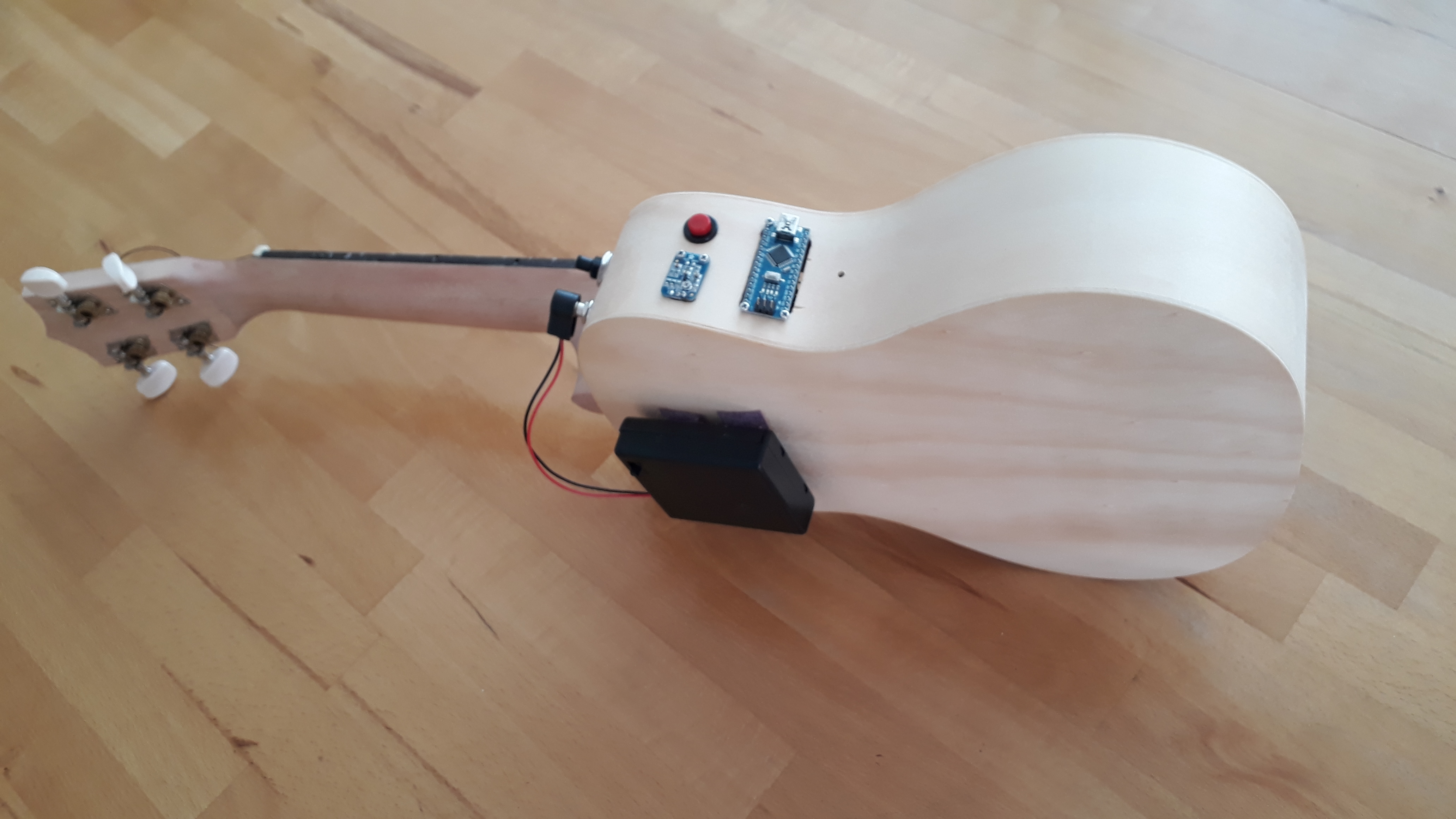
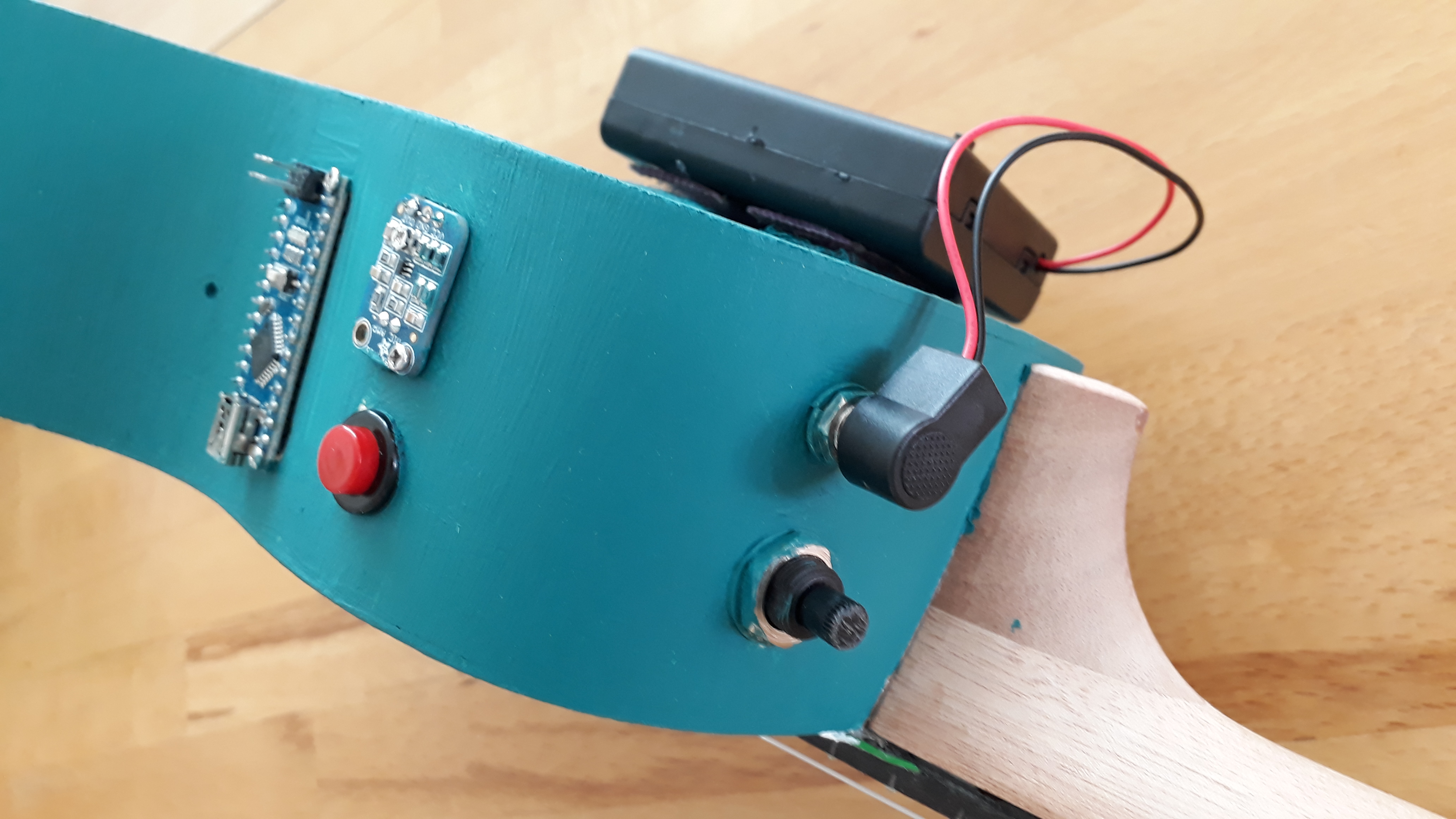
- Embedded Circuitry: The Arduino Nano, power supply (4x AA NiMH), and a brightness-adjusting potentiometer are all integrated into the body, with a custom opening for USB access and mode selection.
- Power Management: A 470µF capacitor is used to stabilize the power line between 3.3V and GND, preventing light flickering caused by processor-induced noise.
Dynamic Interaction Modes
A built-in tactile switch allows the player to cycle through various visualization modes:
- Standard Spectrum: Peaks in audio correspond to visual "leaps" on the fretboard.
- Fire Effect: A simulated burning flame that intensifies with volume and harmonic complexity.
- Solid Color / Manual Mode: Adjustable via the onboard potentiometer for different performance environments.
Hardware
The Ukulele
It all starts with buying an appropriate DIY ukulele construction kit . The following aspects seem most important to me:
- "Size" of the fretboard. Since a certain mounting space for the LED PCBs and the wires is necessary, I went for a concert ukulele (aka "23 inch". Lenght of measure ~38 cm. The most common ukulele, the soprano ukulele, is definitely too small for this kind of project using the electronic hardware described below.). From my "theoretical studies" I thought that the width of the fretboard is ~4 cm at its smallest extent and the distance between the first 10-12 frets (which I wanted to use for displaying the result of the audio spectrum analysis) should also be ~>1 cm for the closest frets (i.e., frets 10, 11, 12). However, if I would repeat this project , I would probably go for the next larger type of Ukulele, i.e., a tenor ukulele , since it turned out that - probably due to manufacturing tolerances and my limited tool set and craftsmen skills - I was not able to follow my original plan. I needed more construction space to get all the LED PCBs in - or smaller LED PCBs. (The LED PCBs I used were about 9-10 mm in diameter and ~3 mm in height).
- UPDATE 1: Meanwhile I found a suitable "larger" (i.e., 23" aka tenor ukelele DIY kit. However it turned out that the width of the fretboard at its upper end is still too narrow to put 4 LEDs in line. Nevertheless it was possible to fit 4 LEDs w/i each of the frets 1 to 11.
- Make sure that you buy a DIY ukulele construction kit that comes with separated neck and fretboard (since in between you will have to put the LED PCBs). W/ respect to the fretboard make sure its thickness (typically 4mm) matches the LED PCBs you choose (in my case LED PCB heigth ~3mm) so that sufficient installation space is provided. Maybe getting 6 mm thick fretboard would also be a good idea mitigating some of the manufacturing challenges.
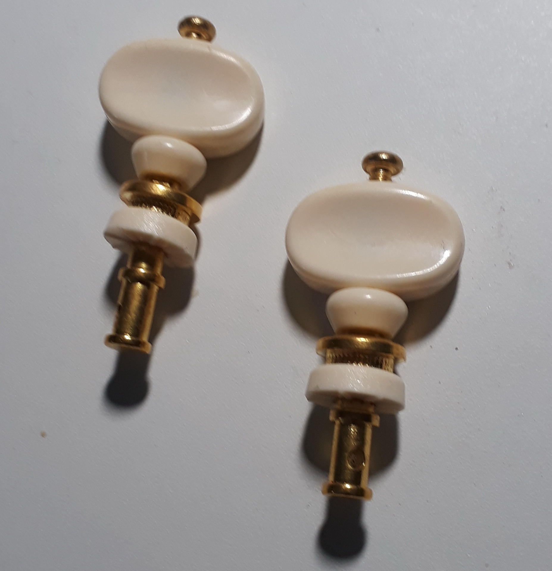
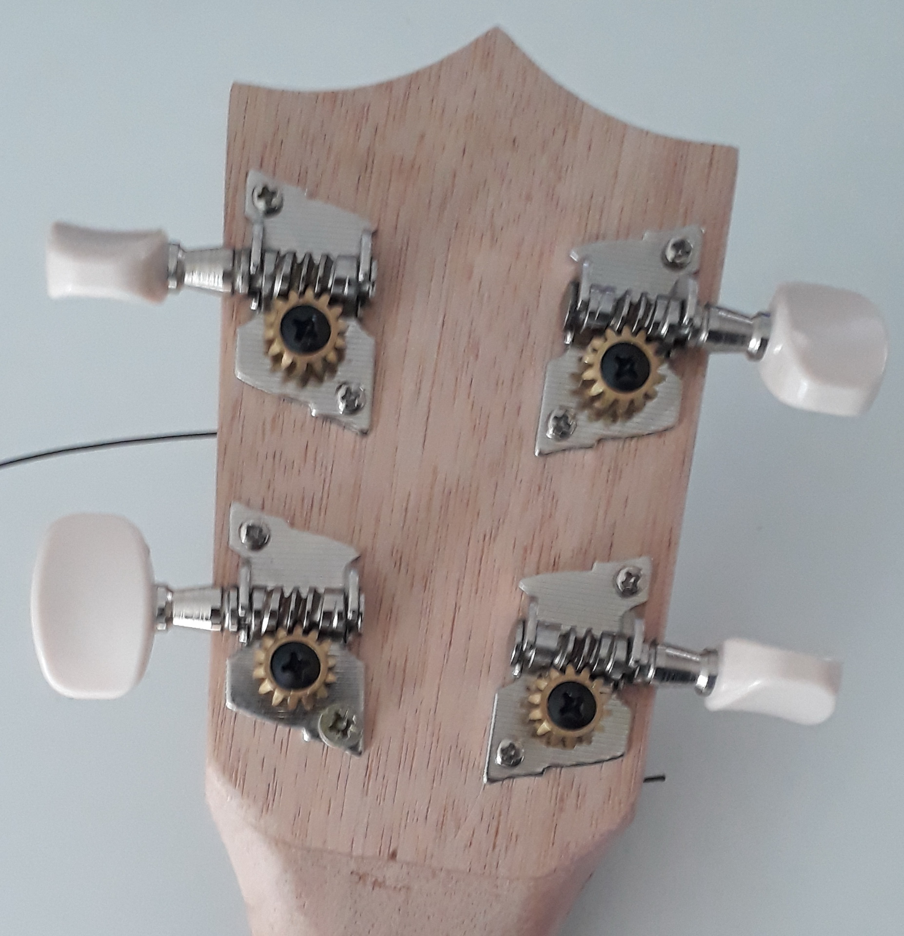
- Most of the DIY construction kits come along w/ rather poor tuning pegs. Those typically easily detune and so you might end up with a nicely illuminated but awfully sounding ukulele. So it might be a good idea to get appropriate tuning pegs along with your DIY ukulele construction kit. What do I mean by appropriate ? There are tuning pegs that basically are straight and other ones that go around by 90° (using worm gear and pinion) in the headstock of the ukulele. Latter ones I prefer. Both types are shown in the images in the gallery below. Attention: There is up to my experience no standard for the diameter of the holes for tuning pegs in the headstock. So make sure you get matching ones. I was lucky since I had some old tuning pegs lying around at home which fitted well enough.
- Last but not least you also might want to get suitable strings , since the ones shipped with some of the construction kits are rather cheap, resulting in - again - frequent detuning and/or poor sound.
Electronics
Due to the limited space available (its a ukulele, not a guitar) I chose an Arduino Nano . Its memory and speed should be sufficient for the audio spectrum analysis and it works w/ the FastLED library used for control of the LED PCBs I connected to WS2812B type strips.
To get the ukulele's sound to the Arduino Nano I decided to use a brakeout board by Adafruit ( Adafruit MAX4466 Electret Microphone ) which records the sound using a broad band electret microhpone and allows adjustment of the gain. Therefore it is possible to adjust the input sound level to the Arduino (since I have no clue how the sound distribution w/i the ukulele's body looks like). Also the package is small enough to meet the requirements w/ respect to limited construction space w/i the ukulele. The 470µF capacitor between Aruino Nano's 3.3 V and GND serves to reduce noise in the 3.3 V power supply line (otherwise resulting in flickering of the 1st two LEDs in each LED strip in the fretboard. Just remove it in your breadboard test setup and you will understand what I am talking about.).
I also added a potentiometer that allows to adjust the brightness of the LEDs. This might come in handy to adjust the LEDs brightness to surrounding light level. Too bright LEDs might be disturbing in a rather dark room. Furthermore, in case your power supply runs empty or all LEDs are lit at maximum brightness, the voltage might drop to a level that leads to unstable operation of the Arduino.
A simple push button was added to facilitate selection of different lightning patterns/operating modes . This can be simply changed (e.g., new combinations added or removed) w/i the software. In case the push button is pressed during execution of the setup part of the code (practically just push it before you power your electronics) all LEDs will turned on and off once to provide a quick way to check functionality of the LEDs/connections to the LEDs.
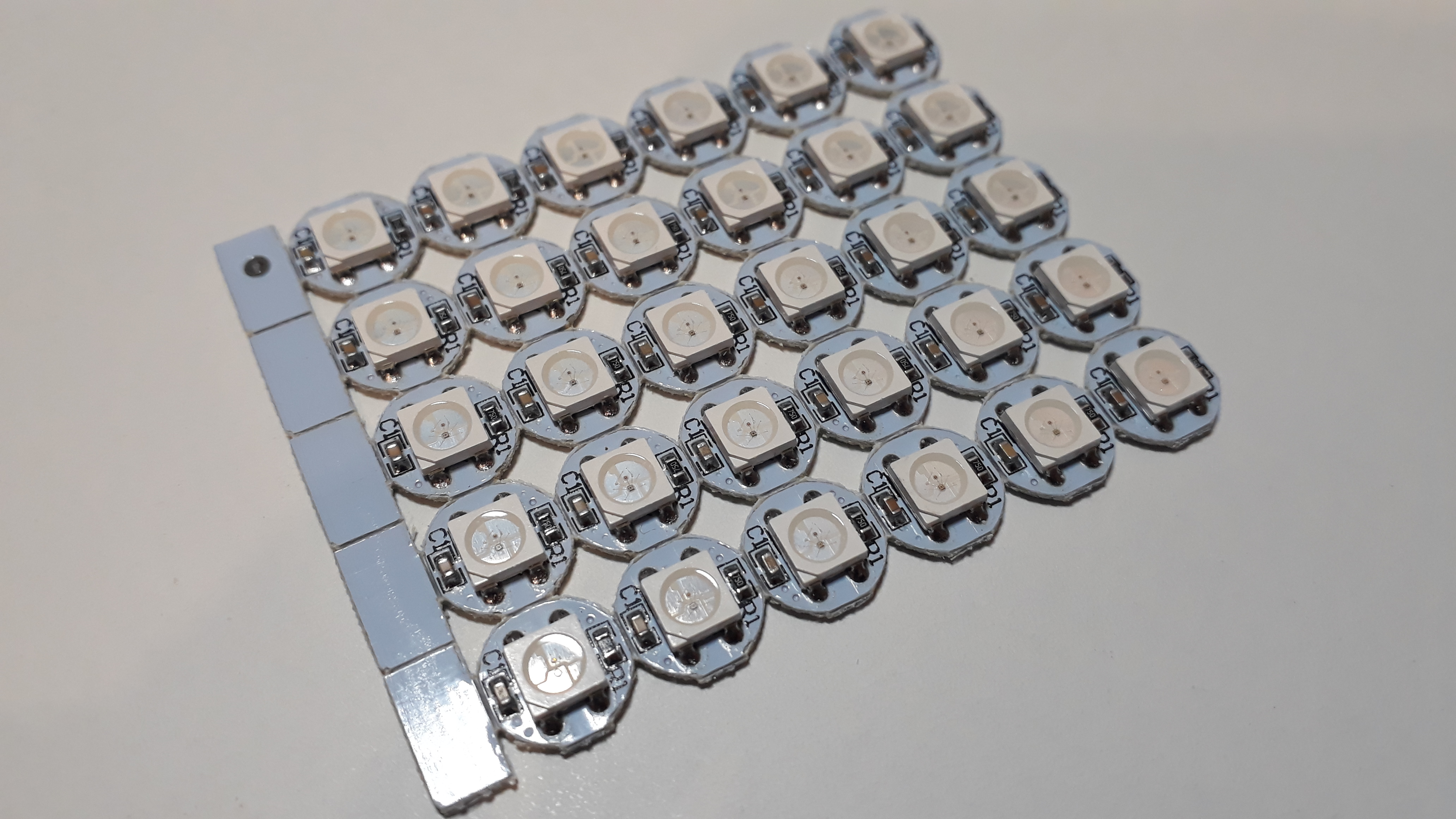
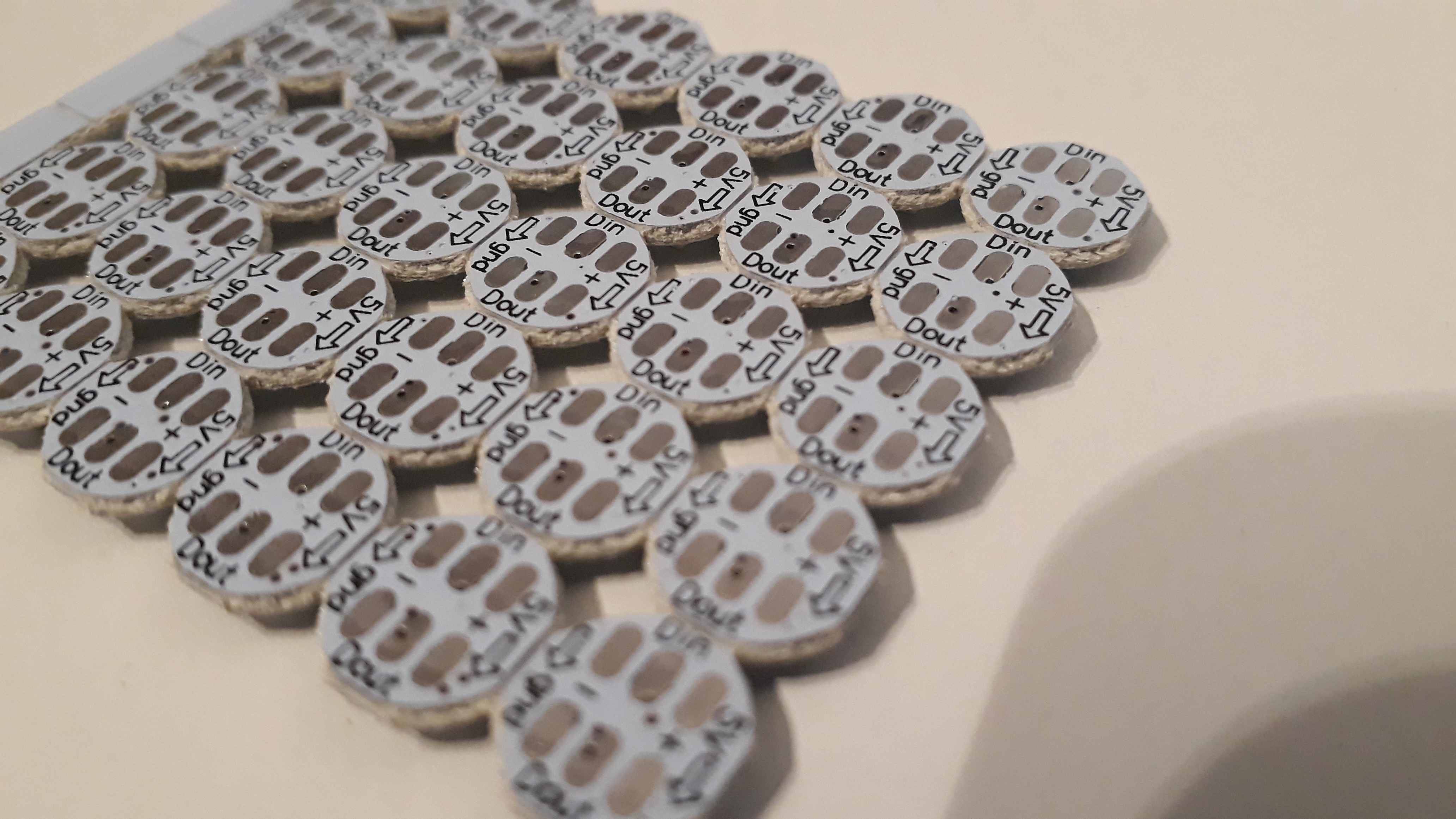
Typical available LED strings (RGB, separately addressable) have equally spaced LEDs. Due to the changing distance between the fret bars this was not a useful approach for my project. I stumbled across single LEDs of WS2812b type (i.e., RGB LEDs, w/ on board WS2811 IC, see picture below) that can be easily controlled using FastLED library just as typical WS2812B LED strings. Make sure the height of these LED PCBs is appropriate for the thickness of your fretboard. Unfortunately I cannot provide a link to the seller since he does not offer such LEDs anymore. :-(
The rest ist wire, solder - and patience.... (Why patience ? 30 LED PCBs w/ 6 closely spaced solder connections each combined w/ limited tool set and craftsmen skills... you'll find out by yourself...)
Manufacturing Part 1: Add LEDs to the ukulele
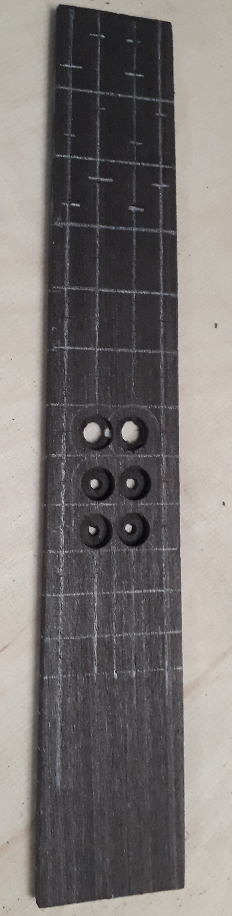
The most crucial and uncertain part to me was whether I could manufacture the fretboard containing the LED PCBs, so...
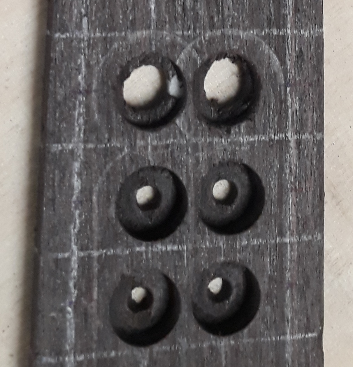
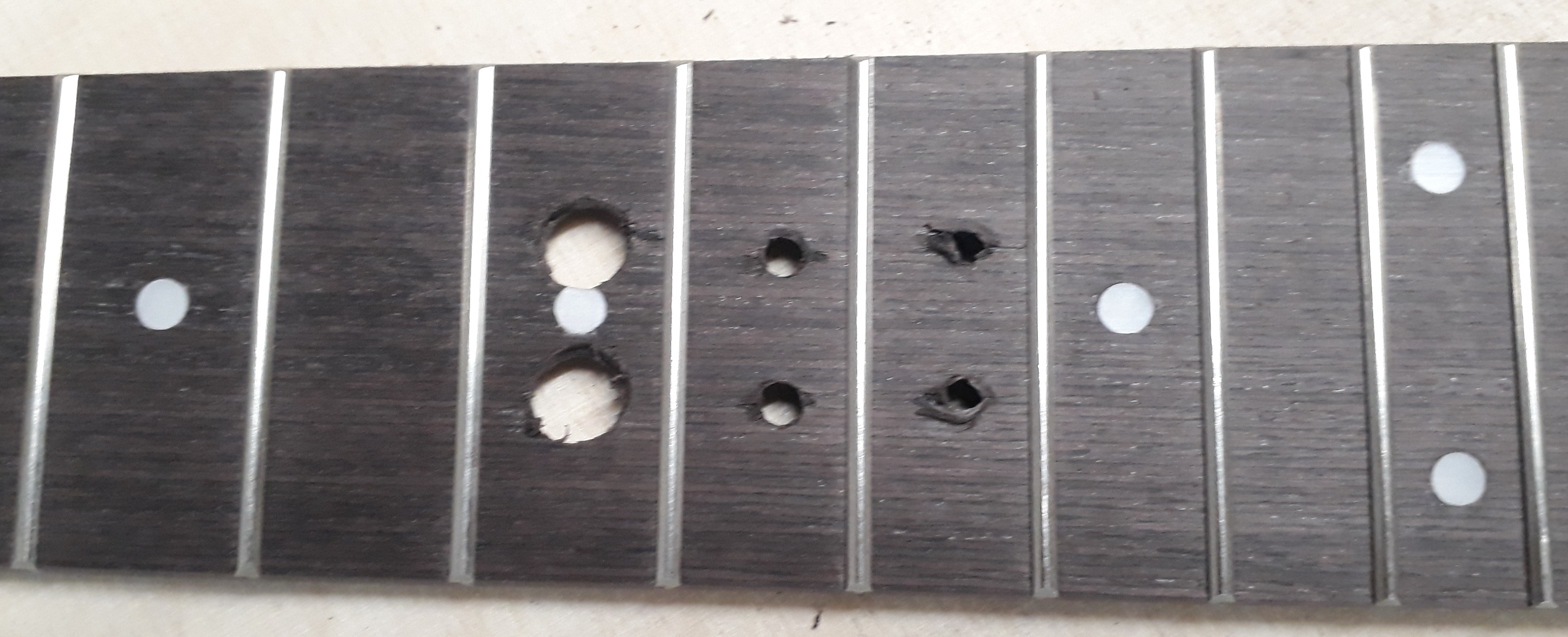
...I started with marking the positions for the LED PCBs on the backside of the fretboard. After that I drilled some dimpels centered at the marked positions and just deep enough so that they can accomodate the LED PCBs from/into the rear side of the fretboard (~3mm in my case). Here a thicker (as above mentioned 6 mm fretboard) would have given me the option to provide some installation space for the solder and wires, however, I only had a 4 mm thick fretboard available.
This is when I also had to realize that especially in the upper, narrow part of the fretboard (frets 1 to 5) I could not achieve the necessary precision to put 4 LED PCBs next o each other w/i one fret. This is why I finally ended up with only 2 LED PCBs in frets 1 to 5 and 4 LED PCBs in frets 6 to 10 (giving a total of 10 + 20 = 30 LED PCBs).
Next, I glued the LED PCBs into the dimples using ordinary handicraft glue. Since the LED PCBs had 6 solder pads (2x GND, 2x VCC, 1x Din, 1x Dout), I decided on the orientation shown in the images in the gallery above. Pay attention to the direction of data flow ! Since there are 2 interconnected GND and VCC pads per each LED PCB, respectively, there is only 1 DataIn and 1 DataOut solder pad, so here the order/direction of connection / orientation of the LED PCB is important. The chosen orientation and alignment allows for straightforward connection of GND and VCC of each LED PCB.
Furthermore (due to the fact mentioned above that I did not succeed in having 4 LEDs in all the frets) I split up the LEDs in 2 seperate optical elements/strings. To save precious installation space GND and VCC for the 2nd LED string are connected directly to an appropriate position of the 1st LED string (thereby saving separate VCC and GND wires for the 2nd string).
Now the fretboard with the LED PCBs has to be mounted to the neck . If one is able to connect the LEDs with wires in a perfect straight line, one could think of milling channels for the cables into the neck. I also tried using copper tape, however due to the topology I did not manage to get sufficient electric contact.
However, as you can see in the images in the gallery below, in my case the wire connections are far from being lined up in a straight way. Furthermore, while the dimples could well accomodate the LED PCBs, the solder however reached out of those dimples. Therefore I decided to use some foam rubber ("Moosgummi") ~2 mm thick. I used multipurpose glue/handicraft glue to glue that foam ruber in between the fretboard and the neck . This is one of the most delicate manufacturing steps, since it is not reversible. Like in case you would just manufacture the ukulele (w/o any LEDs) using the DIY construction kit, you have to compress this triple stack (neck, foam, fretboard) for quite a while and with just the right pressure. Numbers ? No idea. Listen to the craftsman inside you. Also check out the video tutorials if you need information about how to put the pieces together to finally yield a ukulele.
I was quite happy to see that I could still control all the LEDs