The VTTC Staccato Controller was developed in the attempt to create longer sparks from VTTCs while at the same time reducing the input power. The Staccato Controller achieves this by operating the VTTC for a full AC half cycle, then disabling the VTTC for a selectable number of AC half cycles. Basically the controller consists of an oscillator with adjustable parameters and a triac or thyristor at the output of the oscillator, which is connected between the cathode of the vacuum tube and ground.
In the device that I will present to you in this video, an Arduino Nano board is used to build the oscillator, so the device is very simple to build, and yet has many control options. The presented code is very simple and understandable, so if we have some experience in programming, we can expand these possibilities. The original project was taken from teslamuuntaja's blog and I added a two-transistor part so now Mosfet SSTC can also be controlled.
Project Overview & Technical Deep-Dive
This "Tesla-Orchestration" controller is a rigorous implementation of Pulsed-Power Interruption and Synchronous AC-Phase Diagnostics. Designed to optimize plasma-streamer length while minimizing thermal stress on vacuum tubes and semiconductors, it provides deterministic "Staccato" pulses for both Vacuum Tube Tesla Coils (VTTC) and Solid State Tesla Coils (SSTC). Utilizing an Arduino Nano to poll 50Hz/60Hz mains zero-crossing events, the system orchestrates precise trigger-windows for high-voltage Triacs or IGBT-drivers.
- Zero-Crossing & Half-Wave Forensics: The controller ingests a half-wave rectified 12V AC signal via a voltage divider and a 5.1V Zener diode at pin A1. This process involves identifying the rising-edge of each mains half-cycle for temporal synchronization, ensuring the Tesla coil is energized at the optimal point on the sine wave to maximize spark discharge.
- Staccato Pulse-Burst Orchestration: Unlike simple interrupters, this system counts individual AC half-cycles. It allows for "burst-mode" operation, where the coil fires for a deterministic number of cycles before entering a cooling intermission, effectively reducing average input power while maintaining peak performance.
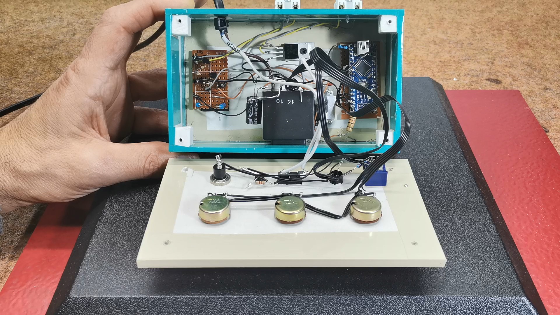
The device is composed of several parts:
- Arduino Nano MCU board
- Three control potentiometers
- Mains transformer with 12V output
- Gretz junction with filter capacitor and voltage stabilizer
- Triac through which VTTC is controlled
- Two transistors for control of SSTC
- and some diodes and resistors
This project is sponsored by PCBWay. They have all the services you need to create your project at the best price, whether it is a school project or a complex professional project. On PCBWay you can share your experiences, or get inspiration for your next project. They also provide completed Surface mount SMT PCB assembly service at a best price, and ISO9001 quality control. Visit www.pcbway.com for more services.

Engineering & Implementation
Now let's briefly explain the working principle. There is a full-wave rectifier on the secondary of the mains transformer, in the continuation of which there is a filter electrolytic capacitor and a voltage stabilizer for 12V. This voltage is used to power the Arduino board. Between the transformer and the rectifier bridge, a half-wave rectified current is taken via a diode to a voltage divider, consisting of two 1 kΩ resistors. After the voltage divider, there is a 100 nF capacitor for filtering, followed by a 4.7-volt Zener diode to limit the voltage to Arduino's maximum of 5 volts. The resulting half-wave rectified and 4.7-volt limited voltage is fed into Arduino's analog input A1.
- Safety Isolation & Filtering Forensics: The logic-hub is powered via an isolated 12V transformer. The 7812 regulator stability and 100nF bypass-capacitor placement ensure the Arduino's analog reference (A2-A4) remains noise-free despite proximity to high-voltage discharges. The Zener diode prevents mains transients from exceeding the Arduino's Vcc rails, maintaining signal integrity at the A1 input without logic-level jitter.
Using this signal, Arduino controls the triac and two-transistor circuit part, which is triggered from Arduino's output D12 through a 220 Ω resistor.
- Triac-Clamping & SSTC Gate-Bridge Integrity:
- VTTC Cathode-Switching Analytics: For VTTC operation, a Triac is placed between the vacuum tube cathode and ground. D12 trigger-pulses "clamp" the cathode to ground during active half-cycles, with design focus on the Triac's dv/dt immunity to prevent accidental latching from EMI.
- Transistor Gate-Driver Harmonics: For SSTC operation, the dual-transistor bridge provides a clean logic-level signal to MOSFET/IGBT drivers, ensuring the interrupter signal doesn't induce parasitic oscillatory switching.
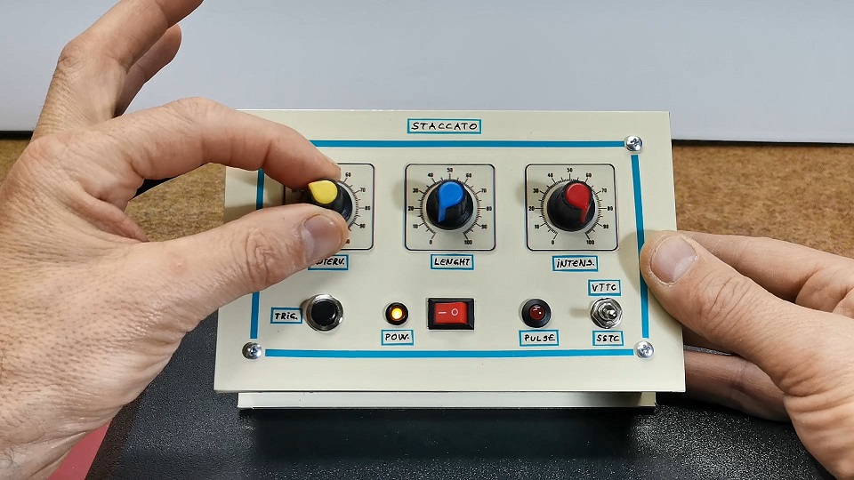
To Arduino analog inputs A2, A3, and A4 are connected three potentiometers that regulate the interval, length and intensity of the generated signal. A button is connected to the D2 pin with pull up resistor. By using the push button, a single trigger can be given. If potentiometer R2 is adjusted to a point where the device does not provide pulses, the push button can be used to give one pulse at a time. LED diode flashes in sync with the triac trigger pulses.

On the back of the device there are two terminals to which the appropriate type of Tesla transformer should be connected, previously selected with the switch. The negative pole in both cases need to be connected to the ground, and the positive pole on VTTC is connected to the cathode of the vacuum tube, while in the SSTC to the Gate of the Mosfet or to the input of the Mosfet driver.
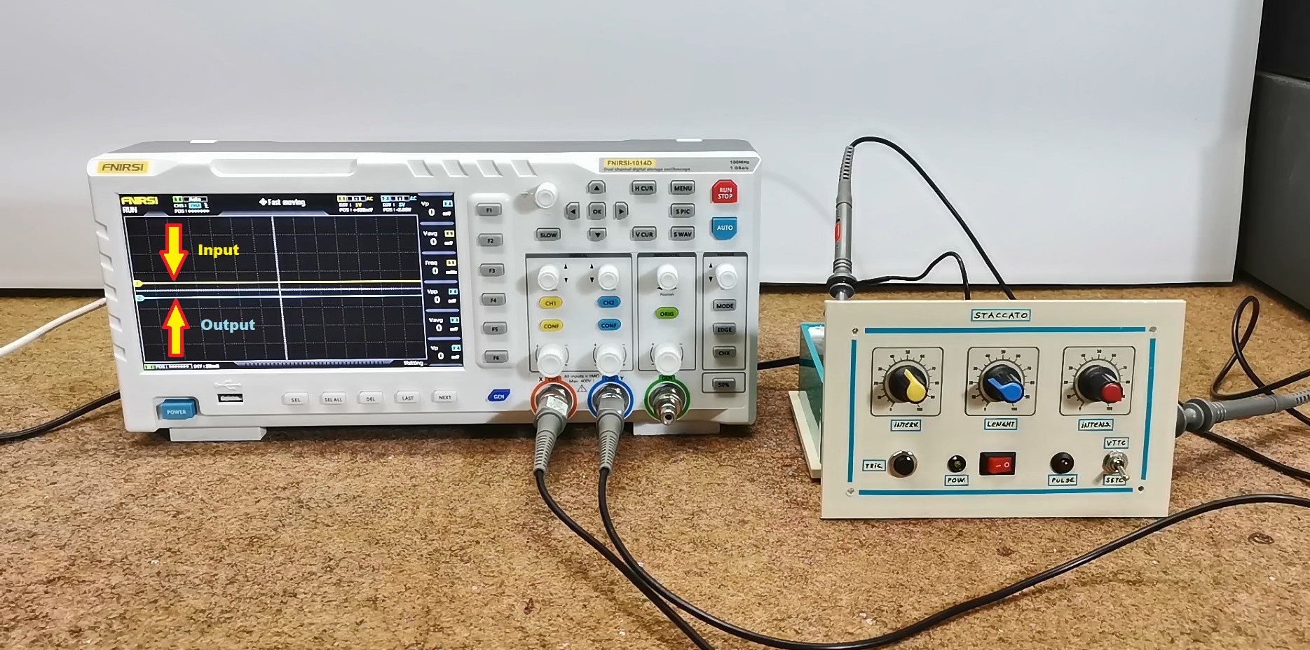
We can best capture the way the device works with the help of an oscilloscope. For this purpose, we connect one channel of the oscilloscope to pin A1, which is the input, and the other channel to the output pin D12.
- Oscilloscope Synchronization Aesthetics: This dual-channel forensic setup is shown in the image below. Channel 1 monitors the rectified AC reference (Yellow), while Channel 2 monitors the trigger-output (Blue). This allows for analysis of the "Intensity" adjustment, which induces a phase-shift in the trigger event, letting the user dial in the exact firing-point on the sine-wave arc.
- "INTERVAL" Potentiometer is used to adjust how often the triac is triggered. When the potentiometer is turned towards one end, the triac is triggered on every half-wave. Near the other end, it's triggered every 50 half-waves, which corresponds to once per second on a 50 Hz power grid.
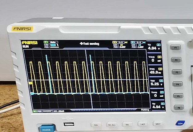
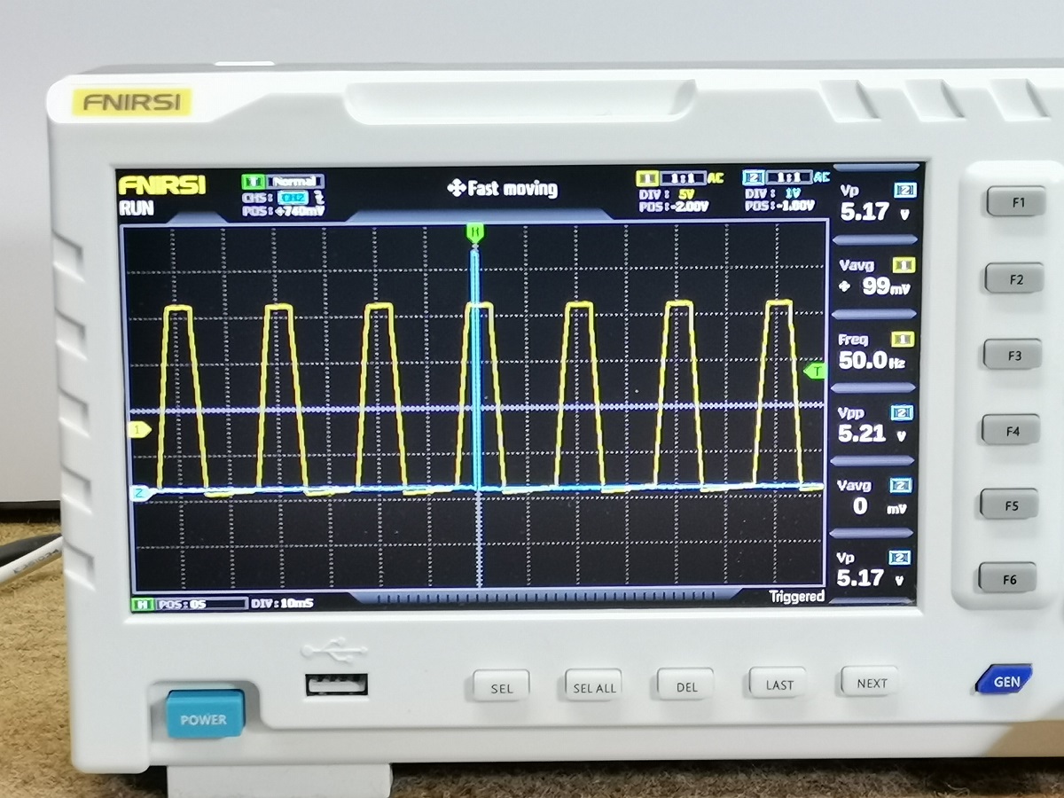
- "LENGHT" Potentiometer is used to adjust how many consecutive half-waves the triac is triggered. The values range from 1 to 25. The oscilloscope images provide a visual representation of this.

- "INTENSITY" Potentiometer is used to adjust the timing of the trigger. This allows for adjusting the intensity of the spark discharge. The most intense discharge occurs when the trigger is given right at the beginning of the half-wave. By adjusting the potentiometer, the trigger timing can be delayed.
Conclusion
And finally, a short conclusion. There are several circuit diagrams for making a staccato controller, but this is probably the simplest way thanks to the use of a microcontroller. Despite its simplicity, the device is incredibly customizable, and with small changes to the code we can achieve a variety of effects.
This project represents the pinnacle of High-Voltage Timing Control. By mastering Zero-Crossing Synchronicity and Staccato Burst-Heuristics, it delivers a robust, professional-grade interrupter that provides absolute plasma clarity through sophisticated phase-locked diagnostics.
At the beginning of the video you can see this device in operation both at VTTC and at SSTC. The entire assembly is mounted in a suitable case made of PVC board with a thickness of 5 mm and covered with colored self-adhesive wallpaper.
Plasma Orchestration: Mastering lightning-telemetry through staccato forensics.