This hydroponics project was a means to become familiar with Arduino devices and programming (the last time I did any coding with enthusiasm was entering pages of hex from the "Your Sinclair" magazine, sorry old time stuff). Anyhow the aim was to replace multiple isolated electronic elements within my hydroponics system with a Wi-Fi enabled micro-controller. This would provide monitoring of various system components locally or via remote platforms. I needed some way to monitor my system as it had a habit of failing using the following equation (severity of failure ∝ distance from shed), normally it was a major leak, dead pump or flat battery. I plan to add a webservice for remote control and a few fail-over routines in the next upgrade.

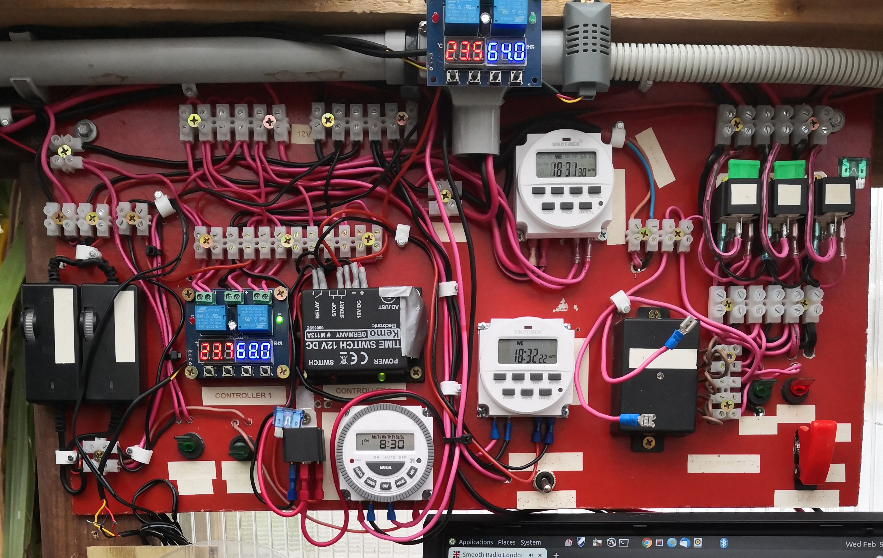
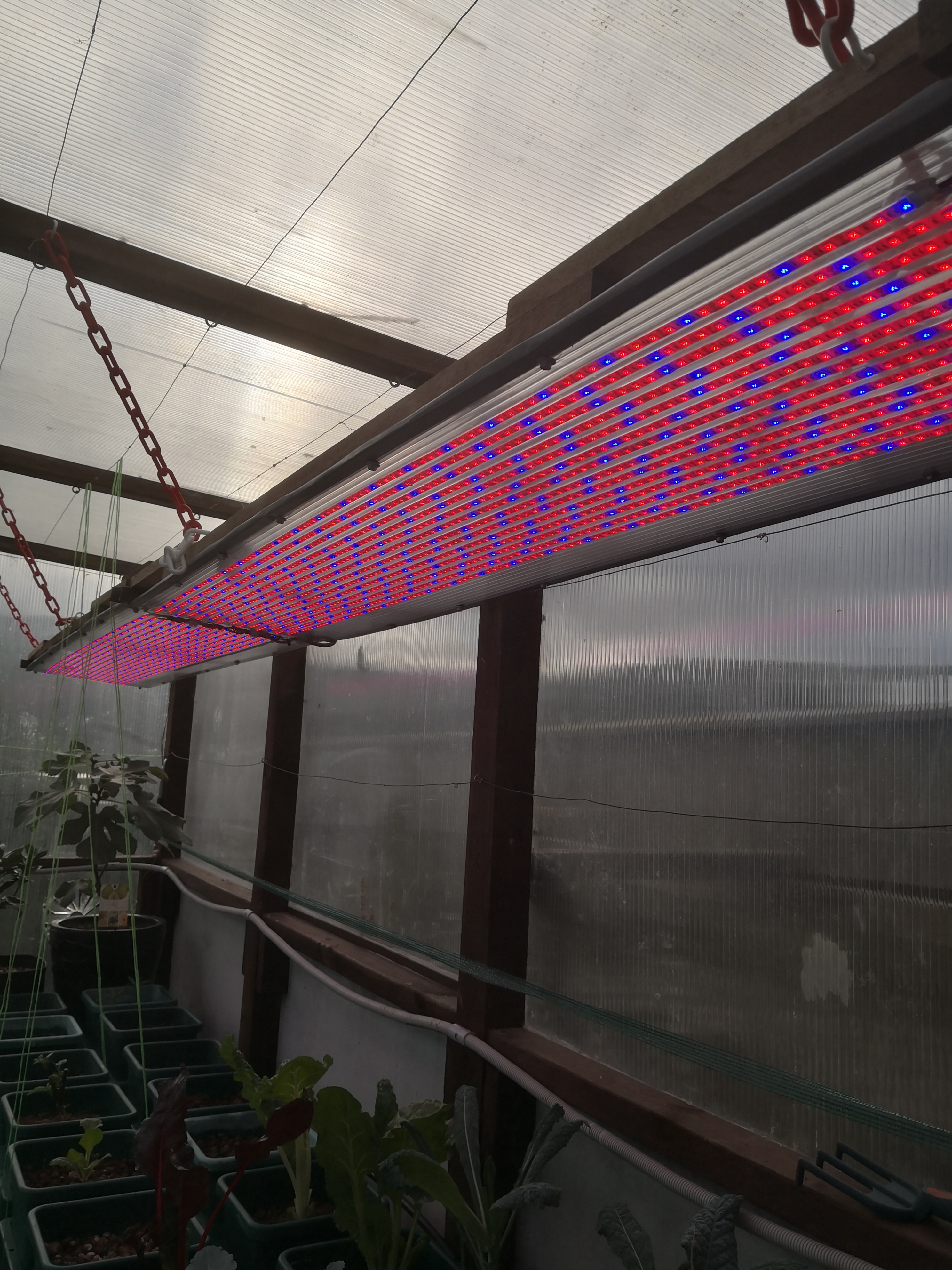
From the above image above you can see a couple of temperature and humidity controllers complete with sensors, 3 electronic timers, 1 time switch, daylight sensor and assorted relays. All these control circulations fans, cooling fans and a nutrient pump. The heavy current relays are for my homemade hydroponic LED lights. The system is power by a N200 lead-acid battery connect to a MPPT Solar Controller and four solar panels, a 20A, 12VDC mains power supply is used for battery back-up and a 40A version powers the LED lights. (10 rolls of strip LEDs each with 300 LED modules, each with 3 sub LEDs per module. Yep that is 9000 little lights and the 12VDC 40A power supply does warm up very nicely).
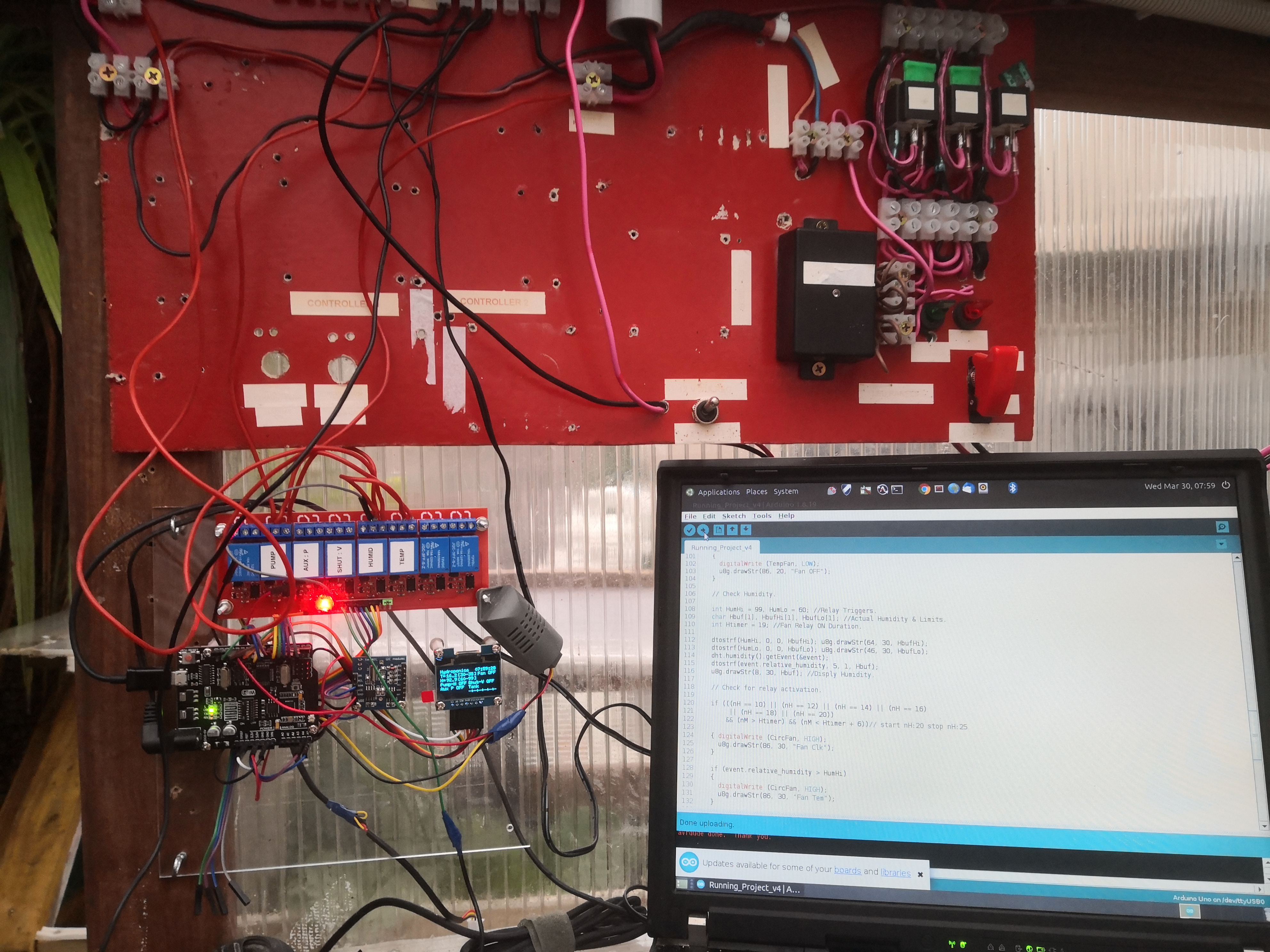
The ATmega328P commands system actions via digital outputs to relays determined by sensor and time data, which are the Real Time Clock and Temperature and Humidity sensors to operate fans, pump and the LED daytime sensor. The logic states are sum of two conditional expressions, the "IF" statement and the Boolean "AND" operation which examines time from the RTC. Each system component is programmed to operate at specific hours over a predetermined minute range, this is to reduces excessive load on the batteries. Sensor data is for monitoring purposes only at this stage. Individual status words are derived from logic states to drive a local OLED display and form part of the final status word string for transmission over the serial bus to the ESP8266 Wi-Fi chip. The ESP8266 parses the data train status information before transmission to a remote Firebase database server via the local Wi-Fi network.
Automated Nutrient Management
This controller stabilizes the complex environment required for soil-less crop growth.
- Hydroponic Sensing: Monitors Water Level using a float sensor and Ambient Humidity using a DHT22.
- WiFi Connectivity: Utilizing an ESP8266 or an Arduino Uno WiFi, the system syncs all sensor data to a cloud database.
Real-Time Database Integration
- Firebase Core: The project connects to a Google Firebase real-time database. This allows for instant updates on a web dashboard or mobile app, providing the farmer with a historical graph of growth conditions and emergency alerts for low water levels.
This is still a work in progress and no doubt I have some odd coding about the place, but it works.