Step 1:You Will Need
REQUIRED HARD WARES :
- Jumper wire
- Joystick Module
- 4 resistor 220 Ohm
- Arduino UNO
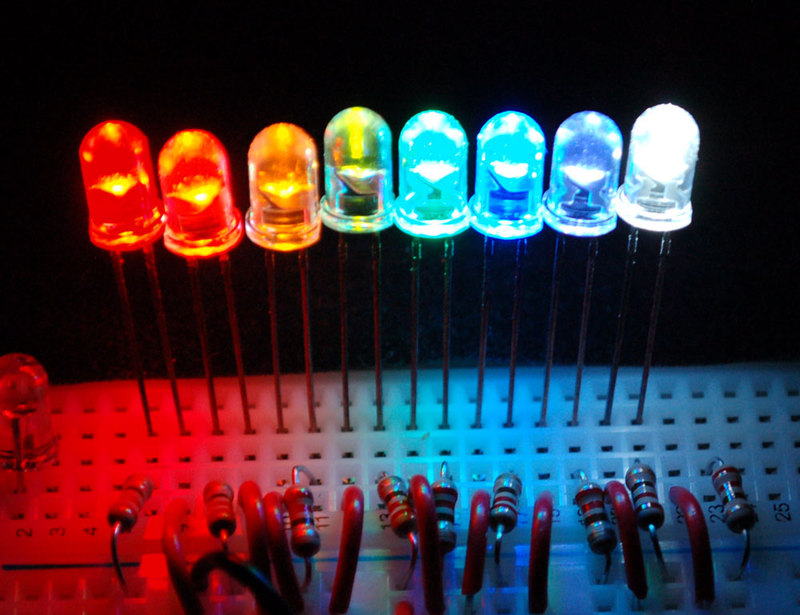
- 4 LED's
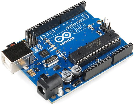
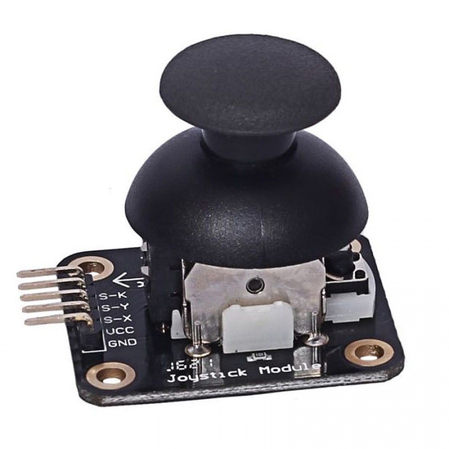
Step 2: Connect Joystick Module to an Arduino Uno
Joystick Module----Arduino
- wire yellow y--------pin A0
- wire brown x--------pin A1
- wire wite bt----------pin 8
- wire red vcc---------5v
- wire black gnd------gnd
Step 3: Connect LED to Arduino
Use the schematic to connect LED to Arduino
EXPANDED TECHNICAL DETAILS
Dual-Axis Analog Control
The standard Analog Joystick module uses two 10kΩ Potentiometers to provide two-dimensional input.
- ADC Sampling: The Arduino's 10-bit ADC reads the voltage on the X and Y pins (0-5V), returning values from 0 to 1023. At the "Neutral" position, both values should be approximately 512.
- Center Deadzone: The firmware includes a small "Deadzone" (e.g., 50 units) to prevent cursor drift caused by mechanical imperfections in the joystick spring.
Interactive Features
- Integrated Pushbutton: Most modules include a Z-axis button (triggered by pressing down on the stick), connected to a digital pin with an internal pull-up resistor.
- Applications: This setup is the foundation for controlling robotic claws, navigating on-screen menus, or building custom USB-HID game controllers for PC gaming.