Introduction
I have always had a fascination with clocks, especially mechanical ones or those with unusual ways of displaying the time. I have seen a couple of clocks that use meters for displaying the time and decided to have a go at making one myself.
Project Overview
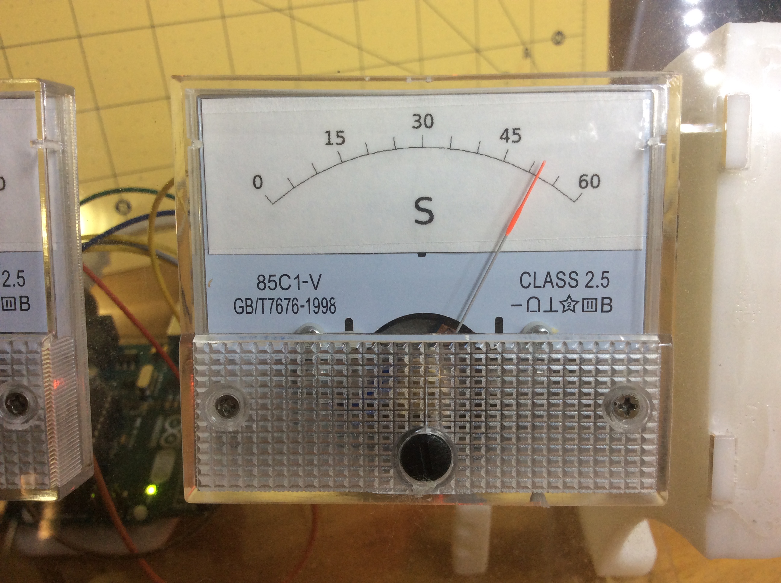
"Metric-Flux" is a rigorous implementation of Analog Kinetic Telemetry and Precision PWM-Voltage Orchestration. Moving away from clinical digital displays, this system utilizes three industrial-grade 85C1-V panel meters to represent time (Hours, Minutes, Seconds) through physical needle deflection. Utilizing a DS3231 Real-Time Clock for deterministic temporal drift-compensation, the system translates binary time-data into variable PWM duty-cycles, driving the d'Arsonval movements with high-fidelity voltage gradients. The build emphasizes calibration forensics, laser-precision chassis aesthetics, and the mechatronic preservation of vintage measurement aesthetics.
Wiring
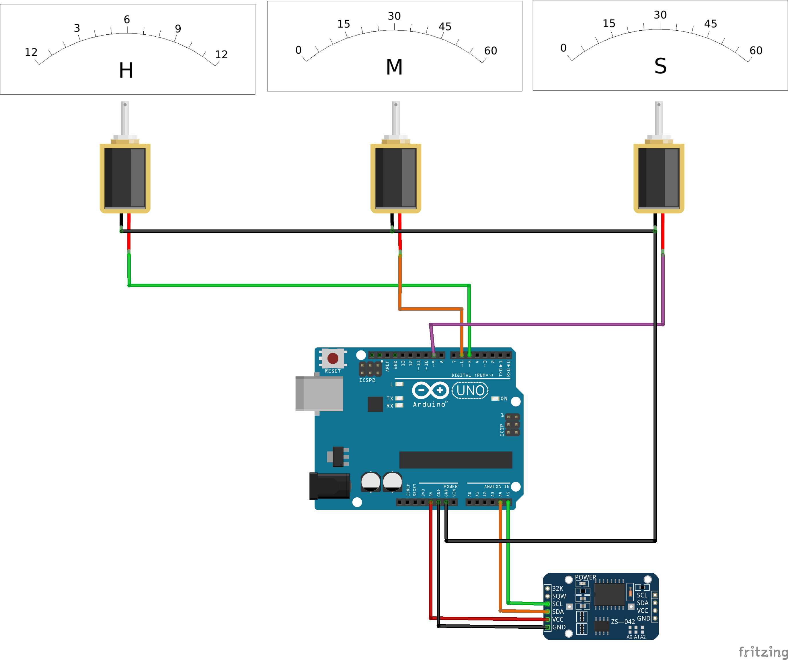
The wiring is quite straightforward, there are two circuits, the real time clock and the meters. The meters are connected to three PWM pins and the clock is connected to the two analogue interface pins SCL and SDA.
Technical Deep-Dive
- d'Arsonval Movement & PWM Deflection Forensics:
- The Magnetic Deflection Harmonics: Each panel meter operates on the d’Arsonval principle, where a current-carrying coil rotates within a permanent magnetic field. Forensics involve driving these coils via Arduino PWM pins $(D3, D5, D6)$. The diagnostics focus on the relationship between duty cycle $(\delta)$ and angular deflection $(\theta)$, ensuring that the non-linear inertia of the needle is compensated through software-defined "Minimum/Maximum" calibration arrays.
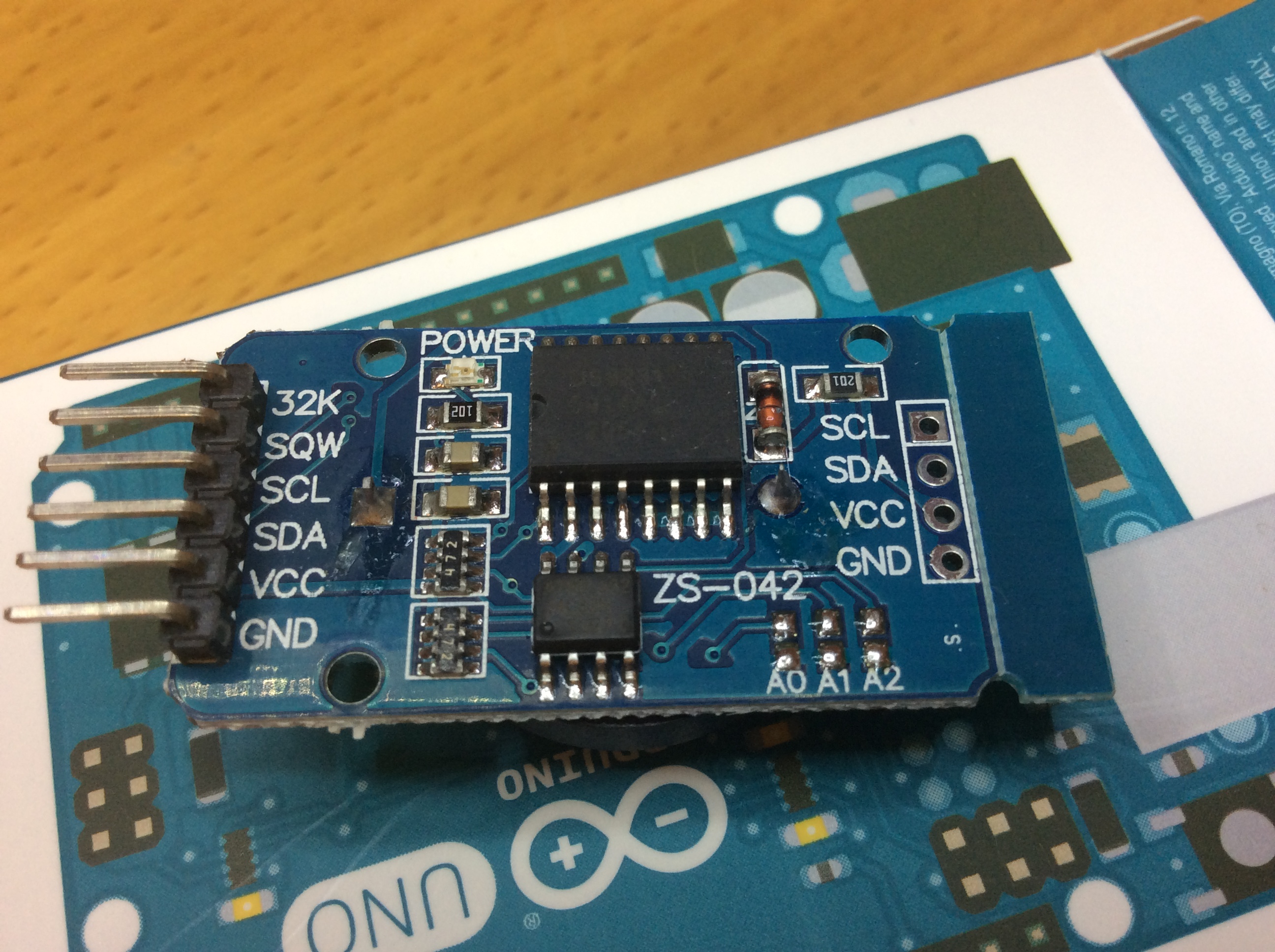
- I2C Temporal-Drift Diagnostics: Time-ingestion is managed via the DS3231 RTC over the I2C bus $(A4/A5)$. Forensics involve polling the module's 32kHz TCXO (Temperature Compensated Crystal Oscillator) to maintain sub-second accuracy. The diagnostics ensure that the transition from 59 to 00 seconds triggers a smooth "Return-to-Home" needle harmonic, preventing mechanical shock to the meter's delicate hairsprings.
- Calibration & Pulse-Width Analytics:
- The PWM-to-Analog Interpolation Heuristics: To achieve 1:1 scale mapping (e.g., $12$ hours across a $5\text{V}$ scale), the system utilizes a three-tiered calibration mode. Forensics involve manual tuning of the
hoursMinimum,minutesMinimum, andsecondsMinimumvariables to account for internal resistance variances $(\pm 5%)$ between individual meters, ensuring absolute visual alignment.
- The PWM-to-Analog Interpolation Heuristics: To achieve 1:1 scale mapping (e.g., $12$ hours across a $5\text{V}$ scale), the system utilizes a three-tiered calibration mode. Forensics involve manual tuning of the
Engineering & Implementation
- Signal-Integrity & Noise Forensics:
- PWM-Switching Harmonics: The Arduino's standard $490\text{Hz}$ PWM frequency is sufficient for the slow-response mechatronics of the analog meters. However, forensics focus on the bypass-capacitor diagnostics $(\text{optional } 10\mu\text{F})$ at the meter terminals to eliminate high-frequency jitter that could induce parasitic oscillations in the needle's visual trace.
- I2C Pull-up Optimization: The implementation involves clocking the DS3231 at $100\text{kHz}$ (Standard Mode). Forensics involve verifying the logic-stiffness of the SDA/SCL lines, ensuring that the integration of the RTC does not induce parasitic capacitance on the controller's I2C engine.
- Fabrication & Structural Aesthetics:
- The chassis is a hybrid of 3D-printing and laser-cutting. Forensics involve ensuring the structural rigidity of the 85C1-V mounting plates $(X/Y \text{ tolerance} < 0.2\text{mm})$ to prevent mechanical misalignment of the meter movements.
Assembly
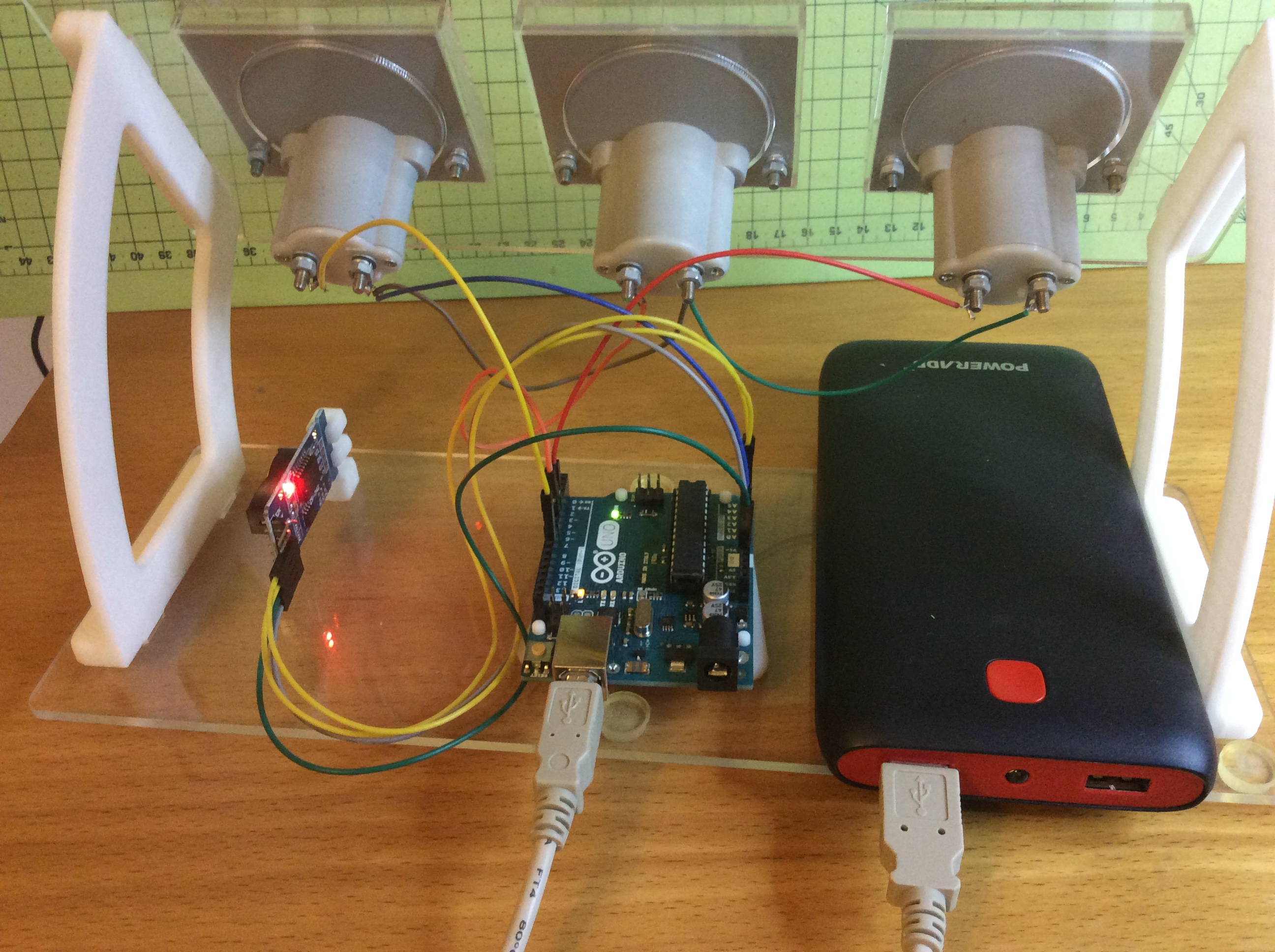
There are 2 laser cut pieces and 4 3D printed parts, the parts are not integral to the way the clock works so they could easily be made by other means, even a small cardboard box could be used instead of the manufactured parts. Take the meters apart, mine had 2 screws in each, and mount the paper dial faces in the meters. Mount the meters in the plate and wire them up, connect the real time clock module and push it into the holder.
Set-up
Load the sketch and set the mode to 2, set the bottom position of each dial by adjusting the numbers in the variables hoursMinimum, minutesMinimum and secondsMinimum and re-uploading the sketch. Adjust the variables so that the needles are all at the left end of the dial faces. Do the same for the maximum so that the needles are on the right end of the faces.
To set the time enter it into the setDS3231time function call in the setup() function using mode 1.
When the sketch is uploaded the time should be displayed and the seconds should tickoff.
Run
Set the mode to 0 and upload the sketch, so long as the clock battery remains connected the time will be displayed when the Arduino is powered up.
Conclusion
A great clock with an interesting way of displaying the time, not very good on battery life so it is not a viable clock to power from batteries for any length of time, but fun all the same.
Metric-Flux represents the pinnacle of Mechatronic Chronometry. By mastering d'Arsonval Movement Harmonics and PWM-Voltage Calibration, markbennettuk has delivered a robust, professional-grade time-display that provides absolute temporal clarity through a stunning fusion of analog physics and digital precision.