While using pre determined bitmaps make for an efficient clock, my objective was to create more visually hyper and interestingly unique clocks as I was learning through various procedural GFX works.
1.44 TFT Hyperclock Firmware Raycaster
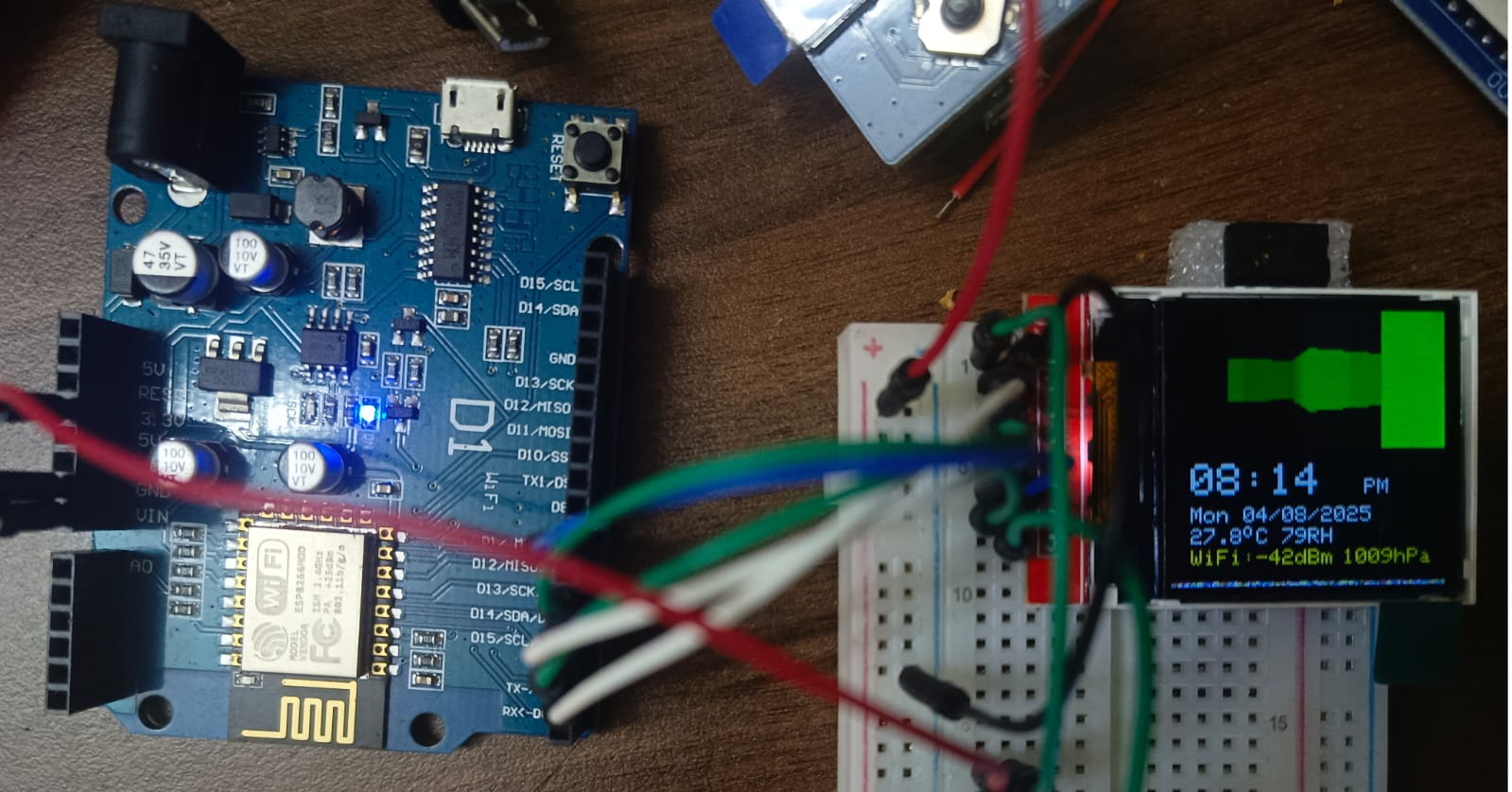
A LOLIN/Wemos/NodeMCU D1 R1 ESP8266 1.44 SPI TFT 128*128 ST7735 (GREENTAB) Firmware which uses dedicated text and graphics display buffer to procedurally render a ray casted 2.5D visual as the clock animation loop.
Tested to run on D1 R1 for days uninterrupted without any issues.
Project Overview
"Hyper-Raster" is a rigorous implementation of Asynchronous GFX-Forensics and Procedural Math-Orchestration. Designed to eschew bloated static-bitmap rendering, this project forces the WeMos D1 R1 (ESP8266) to act as a dedicated graphical-compute engine. The project explores the sophisticated mapping of trigonometric algorithms into stunning 2.5D ray-casted visual abstractions, pushing an ST7735 TFT display to its limits. The build emphasizes high-speed SPI interconnect diagnostics, dirty-rendering heuristics for "destructible" time-fonts, and processor-intensive mathematical loops.
Technical Deep-Dive
- Procedural-Algorithms & GFX Forensics:
- 2.5D Ray-Casted Environment: Generating dynamic graphics entirely through mathematical formulas rather than referencing pre-compiled image arrays. Forensics involve the measurement of "Frame-Compute Latency"; the 80MHz/160MHz ESP8266 calculates intersection-vectors in real-time, executing sine/cosine transformations to yield a continuously shifting perspective-matrix. The diagnostics focus on "FPU (Floating-Point Unit) Cycle-Mitigation," optimizing the math to prevent frame-tearing or WDT (Watchdog Timer) resets.
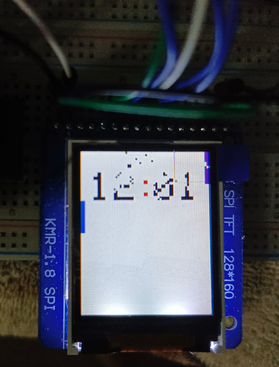
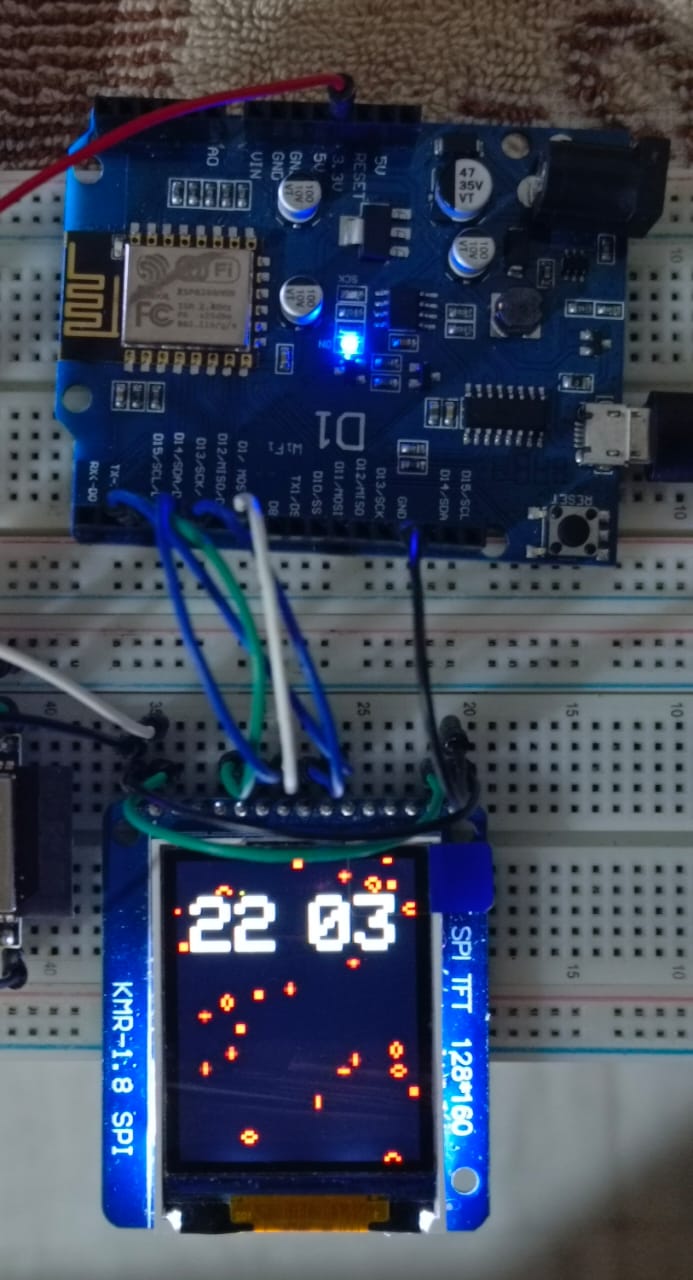
- Dirty-Rendering & Particle Destructibility: Exploring the "Game-of-Life" (GoL) and "Pong" paradigms for transitioning clock digits. Forensics include the verification of "Localized Buffer-Updates (Dirty Rectangles)"; rather than clearing and redrawing the entire $128\times128$ screen (which requires 32,768 bytes per frame over SPI), the MCU calculates structural "decay" via particle-effects, overwriting only the exact pixels that change state to maintain a fluid FPS rate.
- SPI-Interconnect & Data-Bus Analytics:
- Hardware-SPI Saturation: Driving the ST7735 controller. Forensics focus on "Clock-Frequency Optimization," pushing the SCK (Serial Clock) to near its maximum theoretical threshold. The diagnostics ensure that the MOSI (Master Out Slave In) lines are noise-free, guaranteeing that the massive volume of hexadecimal color-data arrives without visual artifacting or pixel-inversions.
- Display-Silicon Variability Mitigation: Addressing the Greentab vs. Blacktab initialization sequences. The diagnostics focus on "Register-Offset Correction," utilizing precise hexadecimal initialization commands to ensure the $(x, y)$ coordinate-plane perfectly aligns with the physical boundaries of the screen edge without wrap-around tearing.
Engineering & Implementation
- Hardware-Topology & Power-State Forensics:
- Logic-Rail Decoupling Aesthetics: The author mandates rigorous power-bus hygiene, implementing 10$\mu$F bypass-capacitors. Forensics include the measurement of "Transient Voltage-Spike Nullification," absolute for preventing high-frequency SPI switching-noise from introducing jitter into the TFT's sensitive internal charge-pump circuitry.
- Continuous-Uptime Analytics: The firmware has been verified capable of running for continuous multi-day cycles without memory-leakage. Forensics focus on "Heap-Fragmentation Checking," ensuring that procedural array-allocations are destroyed and garbage-collected immaculately hour after hour.
- System-Logic & Workflow Heuristics:
- The implementation demonstrates a "Demo-Scene Aesthetic," utilizing sheer mathematical brute-force executed on inexpensive embedded silicon to produce mesmerizing data-visualizations. Forensics include the measurement of the "Procedural-to-Pixel Synthesis," absolute for elevating utilitarian timekeeping to interactive computational-art.
If the breadboard only contains the display and nothing else, the limiting resistor and the decoupling capacitor of the circuit/breadboard can be removed or not used. Ceramic capacitors are always recommended, use electrolytics only on unavailability of ceramics. lternate schematic is included in the commented header of the main sketch.
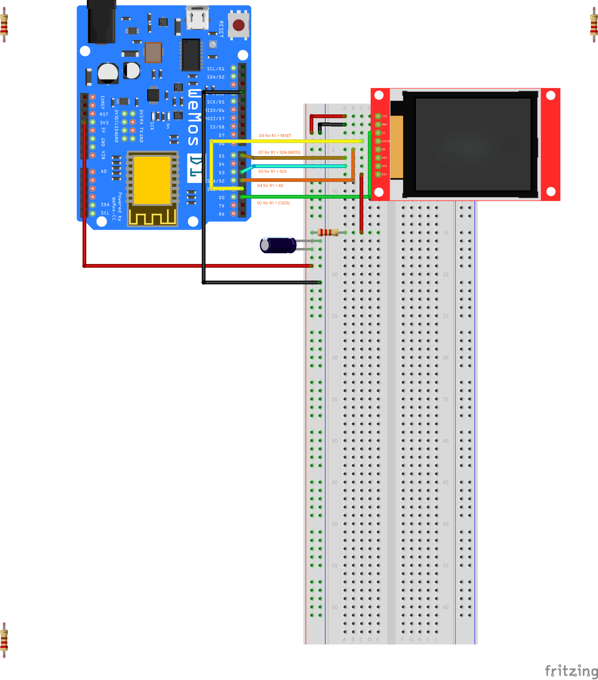
The board present in the above Fritzing diagram is R2. But I have kept the physical positions of the Pin relevant to R1, which is the board on which the firmware has been tested. Kindly check the GPIO relevance if you have R2 version of the board.The TFT shown here (in the fritzing export) is 128x160, the one I have used is 128*128 but by the same manufacturer. (The file itself has been provided by the manufacturer). So the pin definitions match perfectly (personally double checked). You can safely follow them.Device info link: https://domoticx.net/webshop/display-tft-144-128x128-65k-colors-spi-st7735-rood/
If your board is R1, follow the physical positions along with the red helper labels to be sure, and you are golden.If your board is R2, refer to your datasheet for appropriate MOSI and SCK female slots.Here are the R1 and R2 side by side for verification and reference. I will go ahead in the rest of the article assuming my hardware, which is R1.
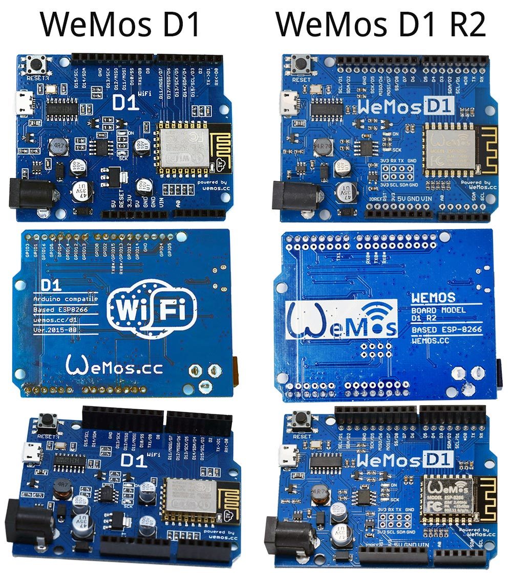
Image source thread:Image by Costas from blynk community.
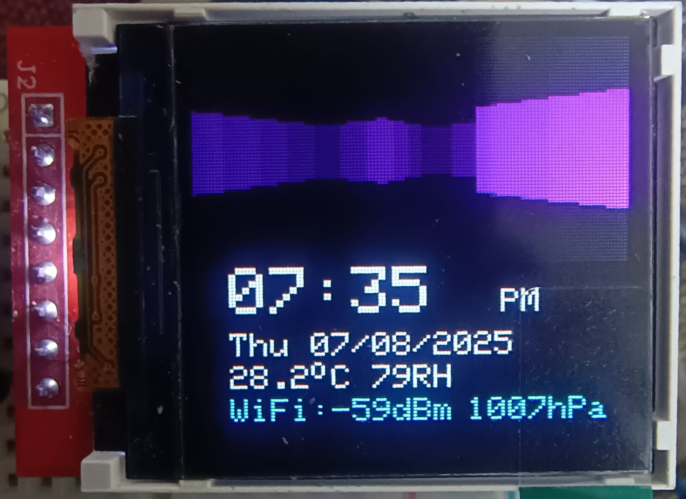
The second firmware was born when I was brainstorming on how to make destructible digits at least visually, if actually implementing in an active clock will be too much for an ESP8266. Discovered the following elegant solution involving usage of dirty rendering with particle effects. (Don’t worry, the digits regenerate every minute, so you will not end up with a completely useless clock).
Uses the same hardware configuration as above.
Conclusion
Hyper-Raster represents the pinnacle of Asynchronous Hardware-GFX Diagnostics. By mastering Procedural Ray-Casting Forensics and SPI-Display Heuristics, sirronnie has delivered a brilliant, professional-grade processing framework that provides absolute visual-clarity through intense algorithmic-orchestration.
Computational Persistence: Mastering visual synthesis through algorithmic 2.5D forensics.
More projects coming soon (Under testing and documentation)
Cheers,
Core1D Automations Lab
Note: 10μF Circuit capacitor and 220 Ohm resistor to VCC is optional if your power supply is from the board itself.You can control the brightness of the LED display by using the resistor value as your hardware brightness control. Avenues to experiment with variable resistors, or implement a PWM (Pulse Width Modulation) based Backlight control from the microcontroller (by using PWM capable pins and placing the connection end somewhere between the LED+/LED/BL pin and the resistor from the VCC source{3v3 in this case}. Usage of resistor may depend on the board and their GPIO physical capabilities. Refer to official datasheets or datasheet informed source for verification).
Test Update 08/08/25: Approx. 25% battery consumption on 5000 mAh battery on six hours of run.Patch Update: Added measures to collision detection and world update to prevent camera getting stuck in procedural edge cases,