How It Works
Use the IR remote to switch between modes:
• Button 1 → Mode 1: Distance and Speed Tracker
• Button 2 → Mode 2: Smart Parking Sensor
• Button 3 → Mode 3: Light Detector
• Button 4 → Mode 4: Clap-Controlled Lights
Each mode runs in real time and uses the LCD to display what’s happening.
________________________________________
Mode 1 – Distance and Speed Tracker
This mode uses the ultrasonic sensor to measure how far something is from it. It also tracks whether the object is:
• Stationary
• Coming closer
• Moving away
If the object is moving, the screen shows how fast it is moving in kilometers per hour.
________________________________________
Mode 2 – Smart Parking Sensor
This mode acts like a car parking sensor. It uses the ultrasonic sensor to measure the distance to an object and gives feedback with lights, sound, and the LCD screen.
Behavior
• From 0 to 50 cm:
Red LED turns on
Buzzer beeps fast
LCD says "close"
• From 51 to 150 cm:
Yellow LED turns on
Buzzer beeps more slowly
LCD says "medium"
• More than 150 cm:
Green LED turns on
No buzzer
LCD says "far"
Customizing It
To change how fast the buzzer beeps, you can adjust the numbers in the code. For example:
if (time_now - previous_time_buzz > 250)
Change 250 to a smaller number to make it faster or a bigger number to make it slower. You can also change the distance ranges to better match your space.
________________________________________
Mode 3 – Light Detector with PWM
This mode uses a photoresistor to measure how much light is in the room.
• If it’s getting dark, the red LED turns on
• The green LED becomes brighter or dimmer depending on the light level using PWM
• The LCD shows both the light level and the green LED brightness
What is PWM?
PWM stands for Pulse Width Modulation. It allows the Arduino to control how bright the green LED looks by turning it on and off very fast. The longer it stays on during each cycle, the brighter it appears. This gives you smooth fading effects.
Customizing It
If the red LED turns on too early or too late, you can change the sensitivity in the code by adjusting the number:
if (light < 300)
Make the number bigger or smaller depending on your room’s normal lighting.
________________________________________
Mode 4 – Clap-Controlled Lights
This mode uses the sound sensor to listen for a clap or loud sound. When it hears a sound:
• All LEDs turn on
• When it hears a sound again, all LEDs turn off
It works like a toggle switch you can control with sound.
Customizing Sensitivity
On most sound sensor modules (like the KY-038 or similar), there's a small blue potentiometer with a screw on top. Turning this screw adjusts the voltage threshold used to decide when the sound is "loud enough" to trigger the digital output (DO pin).
Which Direction Does What?
• Turn the screw clockwise (right):
Increases the threshold → the sensor becomes less sensitive
(It will react only to louder sounds like strong claps or bangs.)
• Turn the screw counterclockwise (left):
Decreases the threshold → the sensor becomes more sensitive
(It will react to quieter sounds like light claps or even background noise.)
Explanation of how the sensors work.
1. Ultrasonic Sensor (HC-SR04) – Measures Distance
The ultrasonic sensor has two round parts: one sends out sound (the trigger), and the other listens (the echo).
When the trigger pin sends out a high-frequency sound wave, it travels through the air and bounces off an object. The echo pin listens for that sound to return. The time it takes for the sound to come back is measured, and the Arduino uses that time to calculate the distance.
________________________________________
2. Photoresistor (LDR) – Measures Light Level
A photoresistor (or LDR) changes its resistance based on how much light hits it.
• In bright light, the resistance goes down, and the voltage read by the Arduino goes up.
• In darkness, the resistance goes up, and the voltage read goes down.
This change is read by the Arduino using an analog input pin, giving you a value between 0 (dark) and 1023 (bright). You can use this value to control when to turn on LEDs or change brightness using PWM.
________________________________________
3. Sound Sensor – Detects Loud Sounds
The sound sensor includes a small microphone and a circuit that detects whether a sound is louder than a certain level.
When a sound like a clap is louder than the set threshold, the digital output pin sends a HIGH signal (1) to the Arduino. If the sound is quieter, the output stays LOW (0). You can adjust the sensitivity of the sensor using the small screw on the module.
________________________________________
4. IR Receiver – Detects Signals from Remote Controls
The IR receiver detects infrared light signals sent from a remote control. Each button on the remote sends a unique code using invisible pulses of light. The IR receiver captures these pulses and decodes them into a number.
The Arduino reads this number and uses it to decide which mode to activate in your project. This allows you to control the whole system wirelessly.
________________________________________
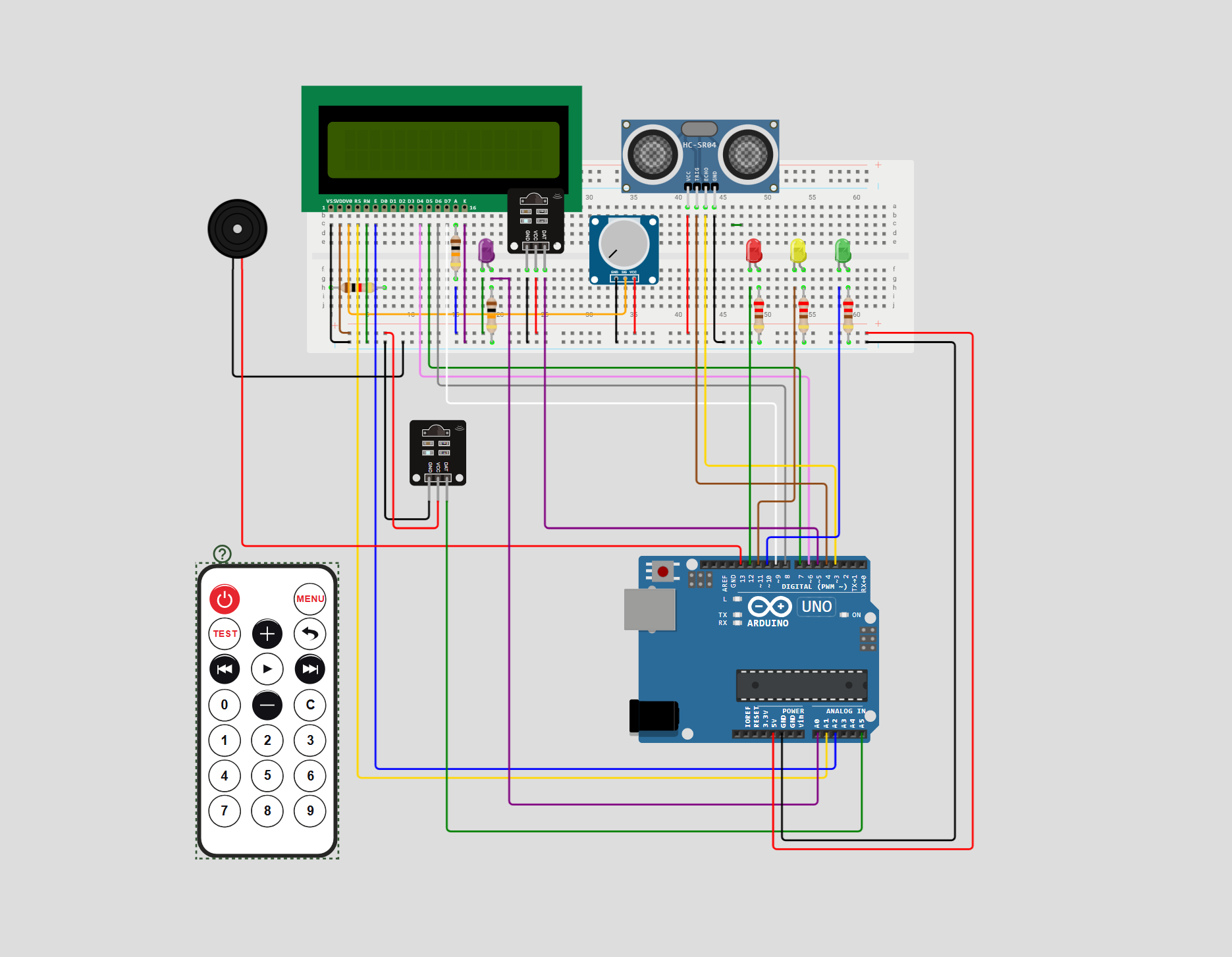
Important Note:
The wiring diagram does not exactly match the real project setup because the online diagram tool didn’t include all the actual components used. In the real project, there is a working photoresistor connected to analog pin A0 to measure light levels. However, because the diagram tool didn’t have a photoresistor part, a purple LED was placed on the breadboard just to represent its position. This LED is not used in the real project—it's only there to visually show where the photoresistor is connected.
Similarly, the diagram tool did not include a sound sensor, so a workaround was used. In the real project, there is one IR receiver, and it is placed on the breadboard and connected to pin 5, where it receives signals from the remote control. However, the diagram mistakenly shows two IR receivers—one on the breadboard (which is correct), and a second one placed off the breadboard. That second IR receiver does not exist in the real project. It was only added to the diagram to represent the sound sensor, since both have three pins (VCC, GND, OUT). In reality, the sound sensor is connected to analog pin A5, and the second IR receiver in the diagram is only a placeholder for it. The extra IR part in the diagram is just a visual substitute because the sound sensor was not available in the diagram tool.
🛠️ เจาะลึกเบื้องหลังการทำงาน (Deep Dive / Technical Analysis)
The Smart Dustbin is a popular beginner project that adds a touch of science fiction to a mundane household item. It perfects the "contactless" experience, which is not only cool but also more hygienic than traditional foot-pedal or manual bins.
![images/projects/expanded/images/projects/expanded/smart_dustbin_open_lid_1772704566789.png)
The Mechanism
The project works on a simple but effective loop:
- Detection: An HC-SR04 ultrasonic sensor is mounted on the front or top of the bin, constantly measuring the distance to any objects in front of it.
- Trigger: If the distance drops below a threshold (e.g., 15cm), it means a hand is nearby.
- Action: The Arduino signals a Servo Motor to rotate, which pulls a mechanical linkage or string to lift the bin's lid.
- Delay & Close: The lid stays open for a few seconds (giving you time to drop the trash) before automatically closing.
Hardware Components
- Arduino Uno/Nano: Small enough to be hidden inside the bin housing.
- Ultrasonic Sensor (HC-SR04): Provides the motion detection.
- SG90 Micro Servo: Powerful enough to lift lightweight plastic lids.
- 9V Battery or Power Adapter: To power the logic and the motor.
- Trash Can: Any small plastic or metal bin with a hinged lid.
![images/projects/expanded/images/projects/expanded/smart_dustbin_internal_servo_1772704583966.png)
Simple Construction
One of the best things about this project is that it can be built with recycled materials. A simple cardboard box or a small desktop bin works perfectly. The mechanical linkage can be as simple as a piece of fishing line or a paperclip, making it a great project for learning the fundamentals of mechanical engineering and automation.