In this project you will learn how to:
- Set up a sensor and retrieve values from it.
- Create timed events without blocking other code from running.
- Produce sound via a buzzer.
Wiring the Modulinos
The Modulino Knob is the primary input for your hourglass. It sets the duration and acts as a start/reset button.
The Modulino Pixels will be used to display the number of minutes selected with the knob. Each minute equals one LED, for every minute added one more LED will light up.
The Modulino Buzzer will be used to give audible feedback so the device notifies you when time is up.
The Modulino Distance is used to control the timer with gestures. Moving your hand close to the sensor will make it act as the button to start and stop the timer.
Wiring diagram
Arrange the Modulino nodes in any order as long as they remain connected via Qwiic cables. It can look like this:
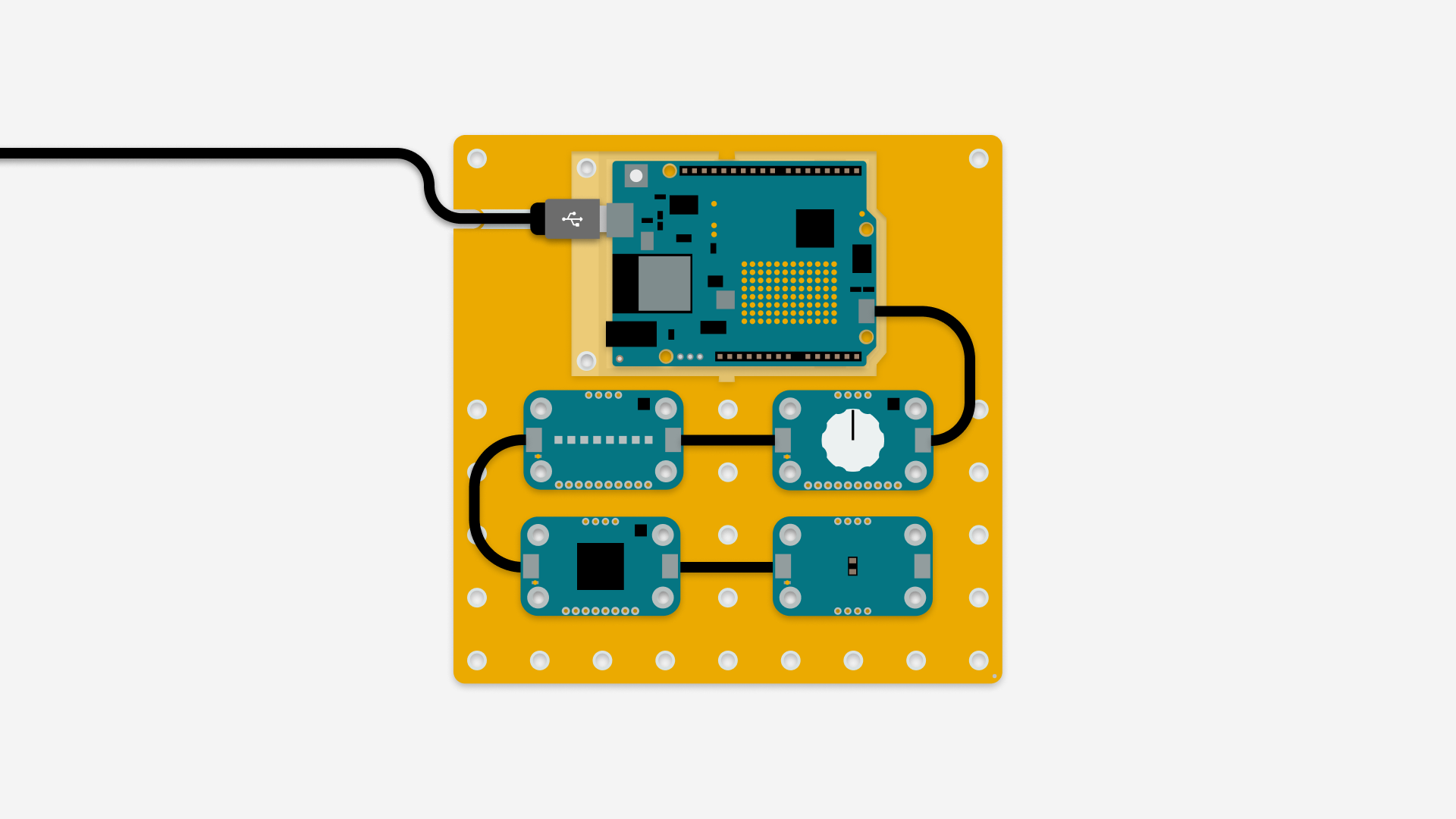
Note: The image shows a UNO R4 board, but any board or shield with a Qwiic connector can be used.
Tidy cables and secure the Modulino nodes so the device is stable. A clean layout makes it easier to debug and nicer to display.
Note: When connecting a Modulino to your board, the orientation and direction do not matter. Just ensure the Qwiic cables are securely and tightly connected. If you need to disconnect the cable, pull gently as close to the connector as possible.
How the project works
- Turning the knob updates the LED indicator.
The Modulino Pixels can display 1–24 minutes with blue, green, and red segments.
- Minutes 1–8 : blue LEDs light up progressively.
- Minutes 9–16 : green LEDs light up progressively.
- Minutes 17–24 : red LEDs light up progressively.
Take the code from the "code" section below and upload it to your board via the Arduino IDE or Arduino Cloud Editor. Make sure you have downloaded the latest board package for the board you are using and the Modulino library if you are using the Arduino IDE.
State machine
A state machine organizes the device's behavior into different states so different logic runs depending on what the device is doing. The hourglass needs three states: Idle , Timing , and Alarm .
The three different states of the device:
- Idle : default state, in this state you can set the time.
- Timing : the hourglass is counting down.
- Alarm : the alarm rings when the countdown ends.
How to transition between the different states:
- Idle → Timing : press the knob while in Idle to start the timer.
- Timing → Alarm : when the timer reaches zero.
- Alarm → Idle : press the knob to stop the alarm and reset to Idle.
Optional Expansions
LED Matrix
If you are using a UNO R4 board, an animation will play on the board's LED matrix. To get this working, take the animation.h file from the "code" section below and put it in the same folder as the main sketch. You can then see an hourglass animation play on the LED matrix whenever the timer is running.
Flip to start
Use Modulino Movement to start the timer by flipping the device like a physical hourglass. In the code there are sections that are commented out, above them it is stated if they are for "Flip to start". If you plug in a Modulino Movement to your Modulino chain and move the sensor it will act as the button to start and stop the timer.
Conclusion
You've built a fully working digital hourglass using a Modulino Knob, a Modulino Pixels, a Modulino Buzzer and a Modulino Movement. A device that can read sensor input, use a state machine, manage timed events without blocking the rest of your code, and provide both visual and audible feedback. The project is modular and ready for creative extensions. Enjoy experimenting!
🛠️ เจาะลึกเบื้องหลังการทำงาน (Deep Dive / Technical Analysis)
The Arduino Kitchen Timer is a project that transitions directly from the workbench to immediate household use. It is robust, easy to operate, and provides a clear, bright digital readout utilizing the classic TM1637 7-segment display module.
The TM1637 Shift Mechanism
Controlling 4 digits (28 individual LEDs) requires a lot of wires. The TM1637 module has a dedicated chip on the back that handles all the heavy lifting.
- It uses only 2 data pins (
DIOandCLK). - You load the
TM1637Display.hlibrary. - Instead of calculating logic gates manually, you just type
display.showNumberDecEx(1230, 0b01000000, true);to instantly print 12:30 on the display (complete with the blinking colon in the center!).
The State Machine (Menubuilding)
The code relies on three main states:
- Setting Mode: The user turns a rotary encoder (or presses Up/Down) to set the starting minutes. The display updates live.
- Countdown Mode: Upon pressing "Start," the variable decreases by 1 every second. Math functions (Modulo
% 60) convert raw seconds into a Minutes:Seconds format. - Alarm Mode: When the variable hits zero, a Piezo buzzer sounds an aggressive, looping alarm until the user hits the "Stop" button.
Hardware Needed
- Arduino Uno/Nano.
- TM1637 4-Digit Display Display.
- Push Buttons (x3) or 1 Rotary Encoder.
- Active 5V Buzzer.