โปรเจคนี้ต่อยอดมาจาก Stage 1 GTT Thermometer ที่เคยทำกันไป คราวนี้เราจัดหนักเพิ่มปุ่มอีก 4 ปุ่ม และเพิ่ม Label แบบไดนามิกอีก 2 ตัว เพื่อสร้าง HMI แบบอินเตอร์แอคทีฟสำหรับตั้งค่าขีดจำกัดอุณหภูมิสูงและต่ำ ตัว Arduino จะคอยอ่านค่าอุณหภูมิและอัพเดทกราฟแท่งกับข้อความบนหน้าจอ GTT อยู่ตลอด ถ้าอุณหภูมิมันเกินขีดจำกัดที่ตั้งไว้ ไม่ว่าจะสูงหรือต่ำ ตัว GTT ก็จะสั่งให้เสียงปีโซ่ (Piezo Buzzer) และมอเตอร์ฟีดแบ็คทำงานทันทีเพื่อเตือนผู้ใช้ งานนี้ห้ามช็อตนะตัวนี้!
มุมมองของโปรเจค
Matrix Orbital GTT TFT Thermometer Stage 2 นี้คือการลงลึกไปอีกขั้นในโลกของจอแสดงผลระดับโปรและการออกแบบ UI ที่แรงๆ ด้วยการโฟกัสที่แกนหลักสองอย่างคือ จอ Matrix Orbital GTT และเซ็นเซอร์ DS18S20 น้องจะได้เรียนรู้วิธีการสื่อสารและสร้างเทอร์โมมิเตอร์ที่หน้าตาดีงามด้วยลอจิกซอฟต์แวร์เฉพาะทางและการตั้งค่าฮาร์ดแวร์ที่มั่นคง งานนี้จัดไปวัยรุ่น!
ลงรายละเอียดเทคนิค: กราฟิกและข้อมูลบน GTT
โปรเจคนี้จะเผยให้เห็นเลเยอร์ต่างๆ ที่ซ่อนอยู่เบื้องหลังการแสดงผลอุณหภูมิที่ดูง่ายๆ:
- เลเยอร์อินเตอร์เฟซ: Matrix Orbital GTT ทำหน้าที่เป็นดวงตาความละเอียดสูงของโปรเจคเรา ให้หน้าจอ TFT สีสันสดใส พร้อมโปรเซสเซอร์ในตัวสำหรับเรนเดอร์กราฟิก
- เลเยอร์เซ็นเซอร์: เซ็นเซอร์ DS18S20 ส่งข้อมูลอุณหภูมิให้ Arduino ผ่านอินเตอร์เฟซดิจิตอลแบบ Single-Wire
- เลเยอร์การสื่อสาร: ข้อมูลถูกส่งจาก Arduino ไปยังจอ GTT โดยใช้ โปรโตคอล I2C
- เลเยอร์ลอจิก UI: โค้ด Arduino ใช้กลยุทธ์ "sequential reporting" คือจะขอและอ่านค่าจากเซ็นเซอร์ทุกๆ 800 มิลลิวินาที แล้วอัพเดทกราฟแท่งและช่องข้อความบน GTT ตามนั้น
ฮาร์ดแวร์ที่ต้องใช้
- จอแสดงผล GTT Series Intelligent TFT
- Arduino Uno
- เบรดบอร์ด
- สายจัมเปอร์ผู้-ผู้ (Male-to-male Jumper cables)
- ตัวต้านทาน 4.7k Ohm (Resistor)
- เซ็นเซอร์วัดอุณหภูมิ DS18S20
- สายเบรดบอร์ด 4 พิน
- สาย USB to Mini-USB
- อะแดปเตอร์ไฟ (ใช้ก็ได้ ไม่ใช้ก็ได้)
ซอฟต์แวร์ที่ต้องใช้
- โปรแกรม GTT GUI Designer
- Arduino IDE
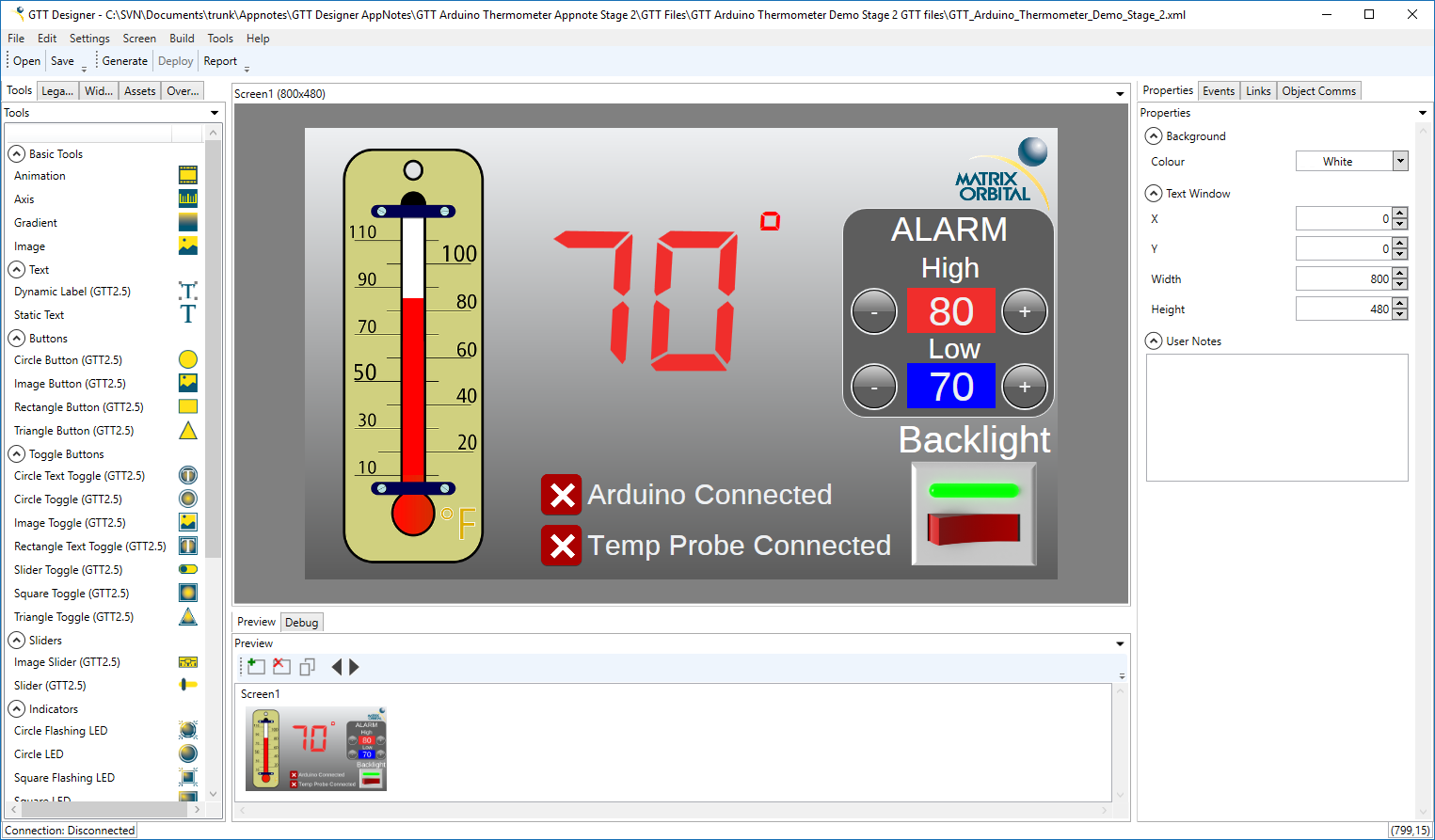
ขั้นตอนที่ 1: ออกแบบ User Interface
เราได้ปรับปรุงโปรเจค GTT Designer จากครั้งที่แล้วสำหรับเดโม่นี้ โดยเพิ่ม Label 2 ตัวเพื่อแสดงขีดจำกัดอุณหภูมิสูงและต่ำ และเพิ่มปุ่มควบคุมอีก 4 ปุ่ม เพื่อให้ผู้ใช้สามารถตั้งค่าขีดจำกัดได้ด้วยตัวเอง เราเปลี่ยนข้อความบนปุ่มเป็น '+' หรือ '-' เพื่อบอกหน้าที่ให้ชัดเจน
ส่วนกราฟแท่ง, สวิตช์อินดิเคเตอร์, และ Label แสดงอุณหภูมิปัจจุบันที่ทำไว้ใน Stage ก่อนหน้าก็ยังอยู่ครบ
เมื่อออกแบบเสร็จแล้ว ก็สามารถ Deploy โปรเจคไปยังจอ GTT ได้เลย น้องจะต้องเชื่อมต่อ PC เข้ากับพอร์ต Mass Storage ของ GTT แล้วกดปุ่ม "Deploy" ใน GTT Designer ไฟล์ที่จำเป็นทั้งหมดจะถูกสร้างและส่งตรงไปยังจอทันที สู้งานนะน้อง!
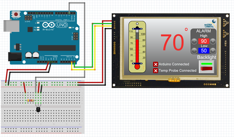
ขั้นตอนที่ 2: ต่อ GTT เข้าไป
เหมือนกับใน Stage 1 เดิมเลยน้อง เราจะยังใช้ I2C ในการคุยกันระหว่าง Arduino Uno กับ GTT ต่อไป ใช้สาย Bread Board Cable ต่อเฮดเดอร์ 4 พินเข้ากับพอร์ต I2C ของ GTT จากนั้นต่อสายสีแดง (Red lead) เข้ากับไฟ 5V และสายสีดำ (Black lead) เข้ากับกราวด์ ส่วนสายสีเหลือง (SDA) กับสีเขียว (SCL) ต้องต่อเข้ากับขา SDA (A4) และ SCL (A5) ของ Arduino Uno ตามลำดับ ไม่ต้องใช้ตัวต้านทานดึงขึ้น (pull-up resistors) สำหรับ I2C ตอนคุยกับ GTT นะจ๊ะ ไฟเลี้ยงเพิ่มเติมสามารถจ่ายผ่านเบอร์เรลแจ็คของจอได้
ขั้นตอนที่ 3: ต่อ DS18S20
ห้ามลืมเด็ดขาด! ต้องใส่ตัวต้านทานดึงขึ้น (pull-up resistor) 4.7k โอห์ม แบบขนานระหว่างขาไฟกับขาข้อมูลของ D18S20 ไม่งั้นเซ็นเซอร์จะคุยกับเราไม่รู้เรื่อง ขาข้อมูลต่อเข้ากับขาดิจิตอลไหนของ Arduino ก็ได้ ในตัวอย่างนี้เราเลือกขาที่ 2
ขั้นตอนที่ 4: ติดตั้งไลบรารี่
ก่อนจะไปต่อ ดาวน์โหลดและแตกไฟล์ไลบรารี่สำหรับ GTT Client ตามด้านล่างนี้ซะ ไลบรารี่พวกนี้ก็หาได้ในไฟล์เฟิร์มแวร์ล่าสุดของ GTT นั่นแหละ พอดาวน์โหลดมาแล้ว ก็อปปี้เนื้อหาในโฟลเดอร์ GttClient ไปไว้ที่ \\Users\\YourUserName\\Documents\\Arduino\\libraries\\gtt ซะ
ไลบรารี่ OneWire ก็จำเป็นสำหรับเดโม่นี้ด้วย น้องสามารถติดตั้งผ่าน Library Manager ใน Arduino IDE ได้เลย ง่ายๆ
ขั้นตอนที่ 5: โค้ด
//GTT Arduino Thermometer Demo Stage 2
//Arduino Uno with Matrix Orbital GTT70A and DS18S20
//Created by Divino, 24/04/2018
//support@matrixorbital.ca
//www.matrixorbital.ca/appnotes
#include <gtt.h>
#include <gtt_device.h>
#include <gtt_enum.h>
#include <gtt_events.h>
#include <gtt_ext_types.h>
#include <gtt_packet_builder.h>
#include <gtt_parser.h>
#include <gtt_protocol.h>
#include <gtt_text.h>
#include <Wire.h>
#include <OneWire.h>
#include "GTT_Arduino_Thermometer_Demo_Stage_2.c"
#include "GTT_Arduino_Thermometer_Demo_Stage_2.h"
#include <stdlib.h>
#define I2C_Address 0x28 //Define default 8bit I2C address of 0x50 >> 1 for 7bit Arduino
OneWire ds18s20(2); //sensor on pin 2
gtt_device gtt; //Declare the GTT device
byte addr[8]; //Buffer to store One wire Address
bool probeConnected; //Bool to determine indicate if the DS18S20 is connected
bool tempSensorReady = 1;
uint8_t maxTemp = 90; //Default Max limit
uint8_t minTemp = 60; //Default Low limit
unsigned long tempTimer;
// Buffer for incoming data
uint8_t rx_buffer[64] = {0};
// Buffer for outgoing data
uint8_t tx_buffer[64] = {0};
void setup() {
//Setup I2C bus
gtt.Write = i2cWrite; //Set the write function
gtt.Read = i2cRead; //Set the read function
gtt.rx_buffer = rx_buffer; //Declare a buffer for input data
gtt.rx_buffer_size = sizeof(rx_buffer); //Declare the size of the input buffer
gtt.tx_buffer = tx_buffer; //Declare a buffer for output data
gtt.tx_buffer_size = sizeof(tx_buffer); //Declare the size of the output buffer
Wire.begin(); //Begin I2C communication
Serial.begin(9600);
delay(100);
resetDisplay();
//Wait for display to reset
delay(3000);
gtt_set_screen1_image_toggle_2_state(>t, 1); //If the Arduino can establish communication with the GTT, toggle the Arduino connection indicator appropriately
gtt25_set_button_clickhandler(>t, MyButtonClick); //Configure the button click handler
setCommunicationChannel(2); //set the communication channel to i2c so button clicks can be returned to the Arduino
tempSensorReady = 1; //Indicate that the DS18S20 is ready for communication
}
void loop() {
if(tempSensorReady){ //If the DS18S20 is ready to start a conversion
probeConnected = searchForTempProbe(); //Search for the DS18S20
startTempConversion(); //Start the temperature sensor reading process
tempTimer = millis(); //Start conversion timer
tempSensorReady = 0; //Toggle SensorReady bool
}
if((millis()-tempTimer)>=800){ //800+ mS after starting the conversion, read the temp
if(probeConnected){ //If the probe is connected
int16_t temp = readTempProbe(); //Read the temperature
char buf[4] = {0};
sprintf(buf,"%d",temp); //Convert the temperature value to a string
gtt_set_screen1_dynamic_label_2_text(>t, gtt_make_text_ascii(buf)); //Update the GTT label
gtt_set_screen1_bar_graph_1_value(>t, temp); //Update the GTT bar graph
//If the temperature exceeds either the high or low limit, activate the buzzer and motor
if(temp >= maxTemp){
Serial.println("Buzzing High");
activateBuzzerAndMotor(1000, 500);
}
if(temp <= minTemp){
Serial.println("Buzzing low");
activateBuzzerAndMotor(500, 500);
}
}
else { //If the probe isn't connected
gtt_set_screen1_image_toggle_3_state(>t, 0); //Set the probe indicator to "Disconnected"
gtt_set_screen1_bar_graph_1_value(>t, 0); //Set the GTT bar graph to 0
gtt_set_screen1_dynamic_label_2_text(>t, gtt_make_text_ascii("NA")); //Update the GTT label to "NA"
}
tempSensorReady = 1; //Temperature sensor is ready for another conversion
}
gtt_parser_process(>t); //Parse for touch events
}
void MyButtonClick(gtt_device* gtt, uint16_t ObjectID, uint8_t State)
{
Serial.println(State);
if (State == 1)
{
char buf[4] = {0};
if (ObjectID == id_screen1_circle_button_1)
{
if((maxTemp-1)>minTemp){
maxTemp--;
Serial.print("maxTemp = ");
Serial.println(maxTemp);
sprintf(buf,"%d",maxTemp); //Convert the temperature value to a string
gtt_set_screen1_dynamic_label_3_text(gtt, gtt_make_text_ascii(buf)); //Update the High limit
}
}
if (ObjectID == id_screen1_circle_button_2)
{
if(minTemp >0)
{
minTemp--;
Serial.print("minTemp = ");
Serial.println(minTemp);
sprintf(buf,"%d",minTemp); //Convert the temperature value to a string
gtt_set_screen1_dynamic_label_1_text(gtt, gtt_make_text_ascii(buf)); //Update the Low limit
}
}
if (ObjectID == id_screen1_circle_button_3)
{
if(maxTemp <110)
{
maxTemp++;
Serial.print("maxTemp = ");
Serial.println(maxTemp);
sprintf(buf,"%d",maxTemp); //Convert the temperature value to a string
gtt_set_screen1_dynamic_label_3_text(gtt, gtt_make_text_ascii(buf)); //Update the High limit
}
}
if (ObjectID == id_screen1_circle_button_4)
{
if((minTemp+1)
minTemp++;
Serial.print("minTemp = ");
Serial.println(minTemp);
sprintf(buf,"%d",minTemp); //Convert the temperature value to a string
gtt_set_screen1_dynamic_label_1_text(gtt, gtt_make_text_ascii(buf)); //Update the Low limit
}
}
}
}
void resetDisplay() {
Serial.println("resetting display");
char command[] = { 254, 1 };
i2cWrite(>t, command, sizeof(command));
}
void setCommunicationChannel(byte channel) {
Serial.println("Setting Communication Channel");
char command[] = { 254, 5, channel };
i2cWrite(>t, command, sizeof(command));
}
void activateBuzzerAndMotor(short frequency, short duration) {
Serial.println("Setting Communication Channel");
char command[] = { 254, 183, (byte)(frequency >>8), (byte)(frequency && 0xFF),