Implementing Multiple Button Switches
Overview
This article offers a highly configurable approach to implementing multiple button switches in a simple, direct but reliable way and using a technique of switch 'polling'.
The article builds on the approach and techniques laid out in a previous publication (a tutorial), namely Understanding & Using Button Switches. The background and basis to the methods offered here are largely those put forward in that tutorial. If it is that you wish for a deeper understanding in the theory and implementation of simple button switches, then please do refer to this tutorial.
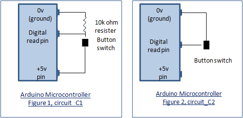
The example sketch at the centre of this article is capable of working with multiple button switches wired in either commonly seen designs - circuits incorporating pull down 10k ohm resistors (see figure 1) or without (see figure 2).
The design of the sketch is such that button switches may be wired in either way or a mixture of both - the sketch may be easily configured to work with either or a mix of both wiring styles.
In summary, the two commonly seen button switch wiring schemes are:
When implementing the sketch it essential to decide which switch wiring scheme is used for each button switch you wish to connect as this has a fundamental bearing and affect on how the inputs are interpreted for switch ON and OFF. If you are unsure then have a look at the tutorial mentioned above, that is Understanding & Using Button Switches.
How Does It Work?
The sketch is able to support many button switches each connected to a digital pin. The number of button switches that can be connected in this way is therefore determined by the architecture of the microcontroller used. For instance, the Arduino Mega 2560 will support literally dozens of digital switch connections - enough for a mock up of the Star Ship Enterprise bridge! However, 'out-of-the-box' (OOTB), the sketch is configured for just six button switches so my UNO is a good choice.
The OOTB sketch has been preconfigured for six button switches, each wired for circuit_C2 - the simplest wiring scheme. But through the configuration of switch data held in a switch control structure, multiple button switches may be efficiently supported, configured in either or a mix of both circuit styles (circuit_C1 and/or circuit_C2).
Once configured, the sketch will poll each declared button switch in turn in accordance with its definition/specification. If a switch press is detected, allowing for debounce, the read function returns a 'switched' status result which is then actioned by a corresponding main loop switch-case statement.
That's it, all very clear, but let's see how we can vary things.
Steps to Implementation
Implementation of the sketch is reasonably straight forward and can be directly worked out by reference to the OOTB sketch. However, the steps to be followed will be:
- decide how many button switches you wish to configure.
- for each button switch decide how it should be wired - either as 'circuit_C1' or 'circuit_C2'.
- wire up the switches according to the above choices and connect to the microcontroller.
- load up the sketch.
- update the macro definition '#define num_switches' to be the number of button switches you are connecting.
- update the macro definition list 'Switch to Pin Macro Definition List' for the button switches you are connecting, one entry for each button switch, suitably defined with a digital pin number. For ease of reading, follow the existing naming structure- see example OOTB sketch.
- now add preset data items for each button switch in the 'Switch Control Sruct(ure) Declaration' ('switch_control'). All entries should be the same as the OOTB entries, the only exception being to data items two ('switch_pin') and three ('circuit_type'). These will be the button switches previously defined and their respective associated circuit type macro definitions.
- finally, for each button switch, decide what you want it to do - see the main loop switch-case section under the polling for loop.
Example
I wish to add a seventh button switch to the existing six switch OOTB sketch configuration and for this to be on digital pin 10 and configured as circuit_C1 (with a 10k ohm pull down resistor). The declarative macro/variable/code changes to the sketch would be:
- define the number of button switches configured as '#define num_switches 7'.
- add a new button switch to digital pin definition to the 'Switch to Pin Macro Definition List'. That is, '#define button_switch_7 10'.
- add new preset data to the 'Switch Control Sruct(ure) Declaration' ('switch_control') for the new button switch. That is,
'button_switch, button_switch_7, circuit_C1, LOW, false, 0, !switched'.
Note that the order of the preset data in this structure is not relevant for decision control/processing - entries can be random.
- include a switch-case section in the main loop to handle your newly added button switch.
Finally
There is a balance to be struck with the number of switches required for a project and the method used to configure them. Whilst this article has largely been instructional, it would prove suitable where switch numbers are not too great. I would most likely look for other methods if the number of switches was, say, more than 10? For example, connecting several switches to a single analogue pin. The wiring scheme would be different and the switch reading process quite different also. No method is perfect and each comes with limitations. Perhaps I will do a future article using this alternative method?
Further Reading
You might also find these contributions interesting and useful, by the same author:
- UnderstandIng and UsIng Button SwItches, the basIcs - button switches, a simple but often tricky piece of kit. The tutorial provides in ins and outs of implementing a simple button switch, with flexibility to explore differences in circuit design, different reading methods and debouncing.
- Interrupts Driven Button Switches - an approach and example of tying a button switch to an external interrupt.
- Toggle Switches - how to reliably read a toggle style switch.
- Buttons & Lights Game - a bit of fun using button switches and LEDs.
- External Interrupts, a generic framework supporting concurrent asynchronous multiple interrupts. Configure multiple external interrupts with different characteristics and add code to provide post-interrupt asynchronous processing.
- Programmatic Timed Reminder Alerting, a programmatic framework for both elapsed and real-time asynchronous alerting. Define any number of reminder alerts (sub second to hours) and process asynchronously.
Other Online Resources
🛠️ เจาะลึกเบื้องหลังการทำงาน (Deep Dive / Technical Analysis)
An Arduino Uno only has 14 digital pins. If you want to build a specialized USB macro keyboard with 20 buttons, you are mathematically out of pins immediately. The Multiple Button Polling via Analog project uses a brilliant feat of electrical engineering—the Resistor Ladder—to compress dozens of physical inputs into a singular, analog mathematical decimal.
The Physics of the Voltage Divider
Instead of giving every button its own digital wire, you daisy-chain them.
- You wire 5 buttons in a row. Between each button, you solder a
1k Ohm resistor. - One end of the chain is connected to
5V, the other toAnalog Pin A0. - The Mechanical Trap:
- If you press Button 1, the 5V power goes through exactly zero resistors.
A0reads1023. - If you press Button 2, the 5V power must flow through one 1K resistor. The voltage drops.
A0reads800. - If you press Button 5, the power flows through four 1K resistors.
A0reads200.
- If you press Button 1, the 5V power goes through exactly zero resistors.
The C++ Threshold Parsing
The Arduino is no longer checking HIGH or LOW. It acts as a digital voltmeter.
int btnValue = analogRead(A0);

if (btnValue > 1000) {
  Serial.println("Button 1 Pressed!");
} else if (btnValue > 750 && btnValue < 850) {
  Serial.println("Button 2 Pressed!");
} else if (btnValue > 150 && btnValue < 250) {
  Serial.println("Button 5 Pressed!");
}
Note: We never use btnValue == 800. Analog electrical resistance fluctuates wildly based on the temperature of the room or the tiny oil on your fingers. You must define generous "Threshold Windows" (between 750 and 850) to prevent ghost-presses!
Component Architecture
- Arduino Uno/Nano/Mega.
- Mass quantities of Tactile Push Buttons.
- 10 to 20 identical Resistors (e.g., all 1k Ohms, or all 10k Ohms) to create uniform mathematical drops in the ladder tree.
- A multi-meter (Critical for debugging why Button 4 is outputting 3.8 Volts instead of 4.1 Volts!).