RC transmitter is very well suitable for the projects requires a wireless link as it has encrypted links with a good range.
All RC receiver is made to drive servo motors. so there are 3 pins for each channel: ground, Vcc, and signal. here a special kind of signal is used. It sends pulses at some interval. When servo receives 1.5ms pulse it sets to 90 degrees and by varying this value from 1-2ms servo goes to minimum and maximum value. (In the above photo a 6 channel receiver is shown with PPM pin)
So easy method is to measuring pulse width on each pin and map that data as per requirement. but here the problem is that:
- For each channel of the receiver, we need to connect a wire to the Arduino pin. This not only requires lots of connection but also consume lots of pins on an Arduino.
- Most of Arduino just has 2 interrupt pin so if we use more than 2 channels read it to add some delay to our code which may be problematic for some application.
To solve this problem many receivers come with an extra pin called PPM. this PPM pin transmits data of all channels in a single signal.
How PPM Pin Signal Composed?
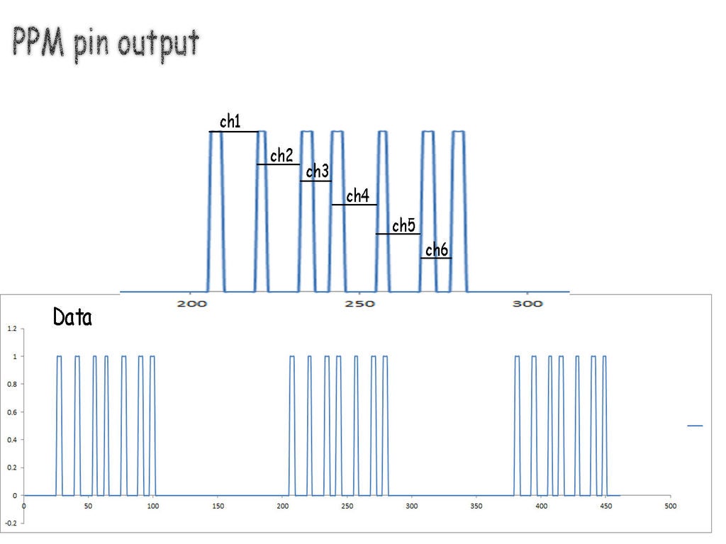
This signal consists of data packets separated by blank space. Here space in between peaks represents the value of the channel. in this case, I have used 6 channel receiver so there are 7 pulses.
So in our code first, we need to detect separation space and then start recording data from the pulses for each channel.
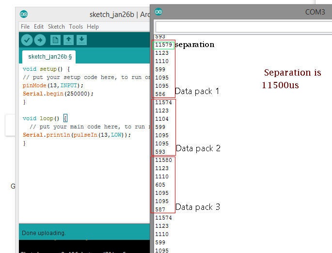
As can be seen in the second image,
all data is separated with approx 11500 microseconds of time. than 6 values are for each channel.
Using the Code:
Here read_me() specified as function:
a=micros(); c=a-b; b=a; x[i]=c; i=i+1;
if(i==15){for(int j=0;j<15;j++) {ch1[j]=x[j];}          i=0;  } }
this part runs on interrupt pin and take 15 time values and store it in an array.
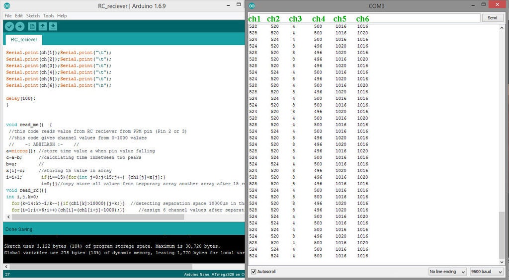
another function read_rc()
this part looks for any space which is higher than 10000microsecond, in our case it detects separation space, and as it detects that space code moves to the next section.
after this space next 6 values are for each channel position it is stored in array named ch[ channel no], here ch[1], ch[2], ch[3], ch[4], ch[5], ch[6] represents value of each channel.
🛠️ เจาะลึกเบื้องหลังการทำงาน (Deep Dive / Technical Analysis)
Wiring an 8-channel standard RC receiver to an Arduino usually requires an insane 8 separate signal wires, consuming almost every pin on the board! This is fundamentally inefficient. The PPM Signal Reader targets elite Drone flight controllers! A modern RC Receiver aggregates all 8 channels into a single, aggressively dense temporal datastream called Pulse Position Modulation (PPM). The Arduino must utilize extreme microsecond interrupt parsing to slice this massive signal into individual joystick angles utilizing just ONE digital pin!
The PPM Synchronization Frame
A PPM frame is a rapid sequence of high/low pulses representing channels (Throttle, Yaw, Pitch, Roll, etc.), followed by a massive "Blanking Space" (over 3000 microseconds) that signals "End of Frame".
- The Arduino uses a Hardware Interrupt (
attachInterrupt()) executing onRISINGedges. - It uses
micros()to record the absolute time since the last rising edge! - If the duration was
1500µs, that's Channel 1 perfectly centered. If it's> 3000µs, the frame is over!
volatile uint16_t rcValues[8];
volatile uint8_t channelIndex = 0;
volatile unsigned long lastMicros;

void ppmInterruptISR() {
  unsigned long now = micros();
  unsigned long duration = now - lastMicros; // How long was the pulse?
  lastMicros = now;

  if (duration > 3000) {
    // The massive sync gap was detected! Reset to Channel 1!
    channelIndex = 0;
  } else if (channelIndex < 8) {
    // Standard joystick pulse (1000us - 2000us)
    rcValues[channelIndex] = duration; // Save the raw stick angle!
    channelIndex++;
  }
}
Validating The Data Stream
Because the interrupts fire relentlessly (hundreds of times a second), the loop() must be very careful when reading the rcValues array.
- You must temporarily disable interrupts (
noInterrupts()) while literally copying the array variables over to the main execution scope, otherwise the interrupt might violently overwrite the variable exactly while theloop()is trying to print it, causing massive data corruption (Tearing)!
Aerospace Hardware Required
- Arduino Uno / Nano (An exact hardware timer and interrupt pin (Pin 2 or 3) is absolutely mandatory).
- Hobby RC Transmitter / Receiver (E.g., FlySky FS-i6, FrSky Taranis) featuring a receiver that explicitly supports PPM output (like the FS-iA6B or D4R-II).
- Servo Motors (To visually test the deciphered output streams immediately).
- A deep understanding of interrupt-safe
volatilekeyword variable manipulation!