Main article: Regulated power supply module based on AMS1117
We often use the power supplies like batteries or direct AC/DC supply which are normally in higher ranges compared to the actual requirement for the circuit. In that cases we need this kind of voltage regulators which can regulate and vary the voltage levels for the circuit requirement.
The AMS1117 series of chips are linear voltage regulators with low voltage drop. The modules based on the AMS1117 chip provide constant 3.3V or 5V outputs from an unregulated DC input. It's very compact and can be included in your project schema or you can use it together with a breadboard for circuit testing.
Wiring schema
The connection is pretty easy, it only has VIN (input voltage), VOUT (output voltage) and GND.
The input voltage may vary depending on our module:
- Module with 5V output: VIN should be 6V-12V
- Module with 3.3V output: VIN should be 4.5V-7V
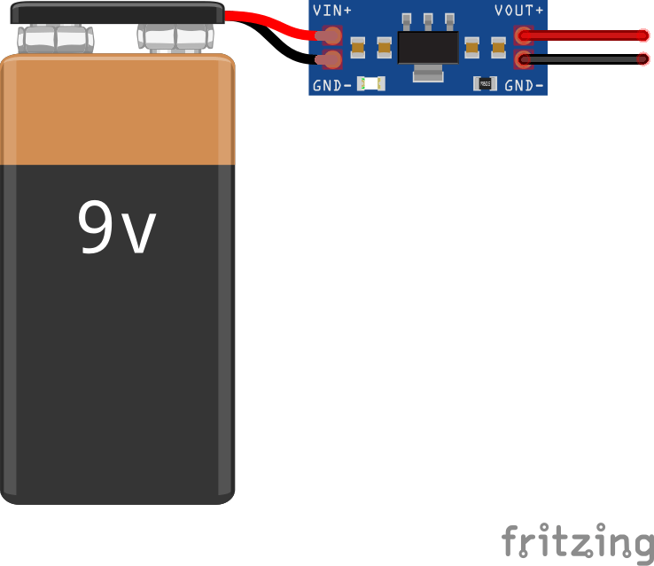
Note: output current must not exceed 800mA.
Conclusion
This is how we can use AMS1117 in circuits where voltage regulation is needed. It's very useful in electronic developments where external modules are used and a separate power source is required. This is an excellent device which can control voltages without altering the power levels in the circuit as well as it doesn’t consumes any extra power.
🛠️ เจาะลึกเบื้องหลังการทำงาน (Deep Dive / Technical Analysis)
If you run an ESP8266 Wi-Fi chip and an NRF24L01 radio off the specific 3.3V pin of a standard Arduino Nano, the massive power demand (400mA) instantly obliterates the tiny internal FTDI regulator! The Nano will aggressively reboot infinitely. Engineering the AMS1117 Regulated Power Supply completely bypasses the weak, internal Arduino silicon by physically building a massive standalone 800mA Step-Down linear transformer expressly designed to cleanly convert 5V USB (or 12V Batteries) into perfectly flat 3.3V logic flow!
The Physics of Linear Heat Dispersal
A linear voltage regulator works by mathematically converting the "Extra" voltage directly into raw heat (Thermodynamics!).
- If you pump
12 Voltsinto an AMS1117-3.3, it violently snips8.7 Voltsoff the top. - If the sensors pull
500mAof current:Power (Watts) = 8.7V * 0.5A = 4.35 Watts of pure heat! - The Catastrophic Failure Mode: The extremely tiny copper tab on the back of the AMS1117 cannot absorb 4 Watts of fire. Within 10 seconds, it will reach 150°C and "Thermal Shutdown."
- The Engineering Fix: You MUST drop the input voltage first using a switching regulator, or feed the AMS1117 exclusively from a
5Vsource so it only has to aggressively discard1.7V(which is barely 0.85 Watts, keeping the chip perfectly cool!).
The Filtering Capacitor Array Matrix
The AMS1117 does not work correctly if you just plug it into a battery alone. The output will oscillate violently like a radio antenna!
- The physical hardware datasheet mandates explicit capacitor bounds!
- You absolutely MUST solder a 10uF Tantalum Capacitor on the Input (
VIN to GND). - You MUST solder a 22uF Tantalum Capacitor on the Output (
VOUT to GND). - The Physics: As the ESP8266 Wi-Fi chip draws a massive 400mA spike when connecting to the router, the tiny AMS1117 silicon cannot react fast enough. The
22uFoutput capacitor acts as a massive bucket of stored water, violently dumping electricity into the Wi-Fi chip for 10 milliseconds to stabilize the voltage until the regulator catches up!
Hardware Transformer Needs
- AMS1117-3.3 Linear Regulator (SOT-223 Package).
- Two Physical Filtering Capacitors (Values according to explicit Datasheet tolerance specifications).
- Basic Perfboard or simple PCB Design (The massive exposed solid copper tab on the back MUST be soldered heavily onto a huge pad of copper on the PCB—that trace literally acts as its physical heat-sink!).