INTRO
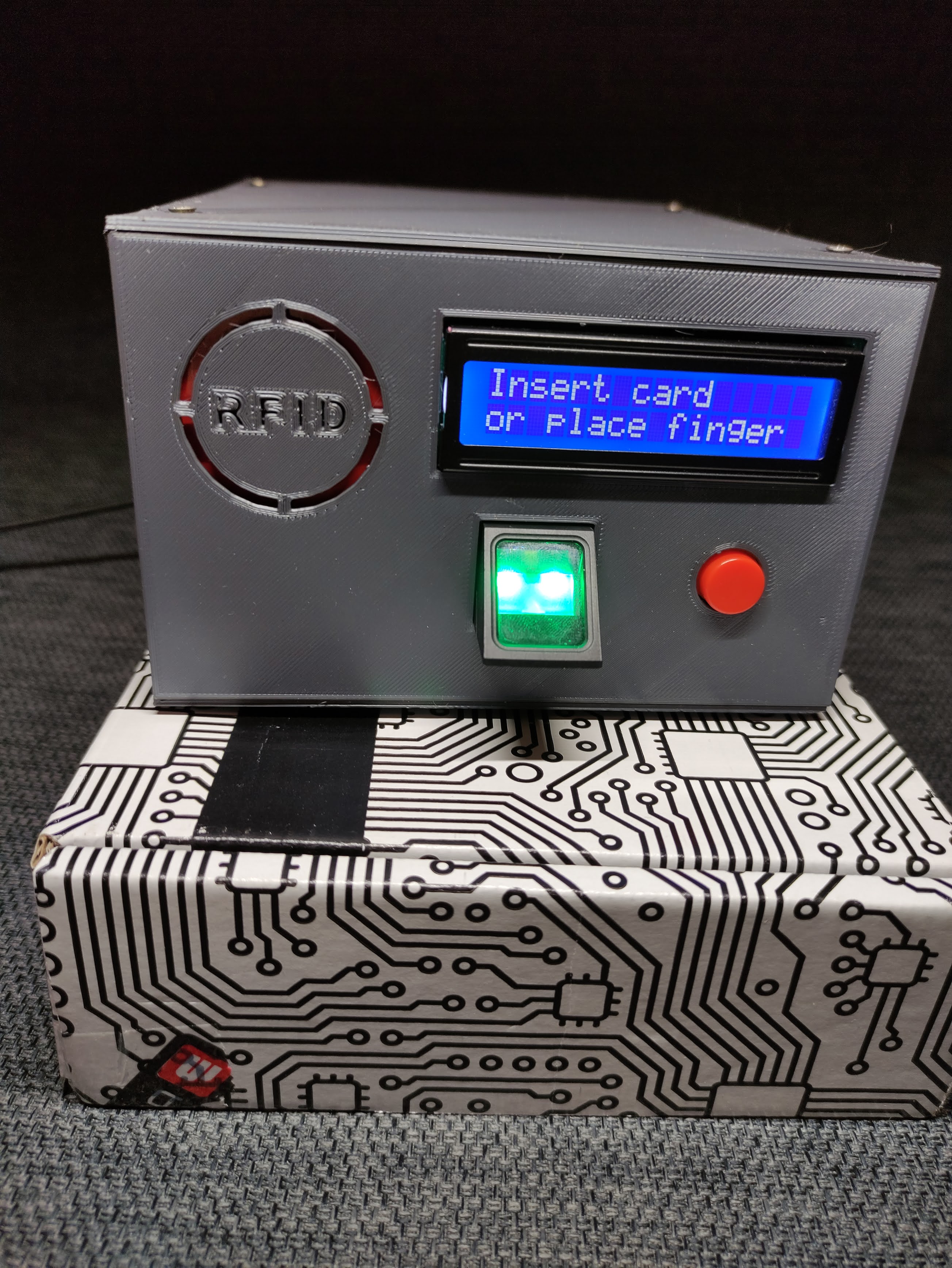
This is a project I made for my microprocessor programming laboratory at my university. The project goals were to log in and out of my PC using RFID card or fingerprint scan.
I value privacy a lot, so ability to log in and out in mere seconds, without typing password is a life saver for me. This interface is fully open source, you can use it and modify as you please.
Two very important things here:
You can use this project with only RFID reader with absolutely no changes in code, but using it with only fingerprint scanner require full code rebuild.
WIRING
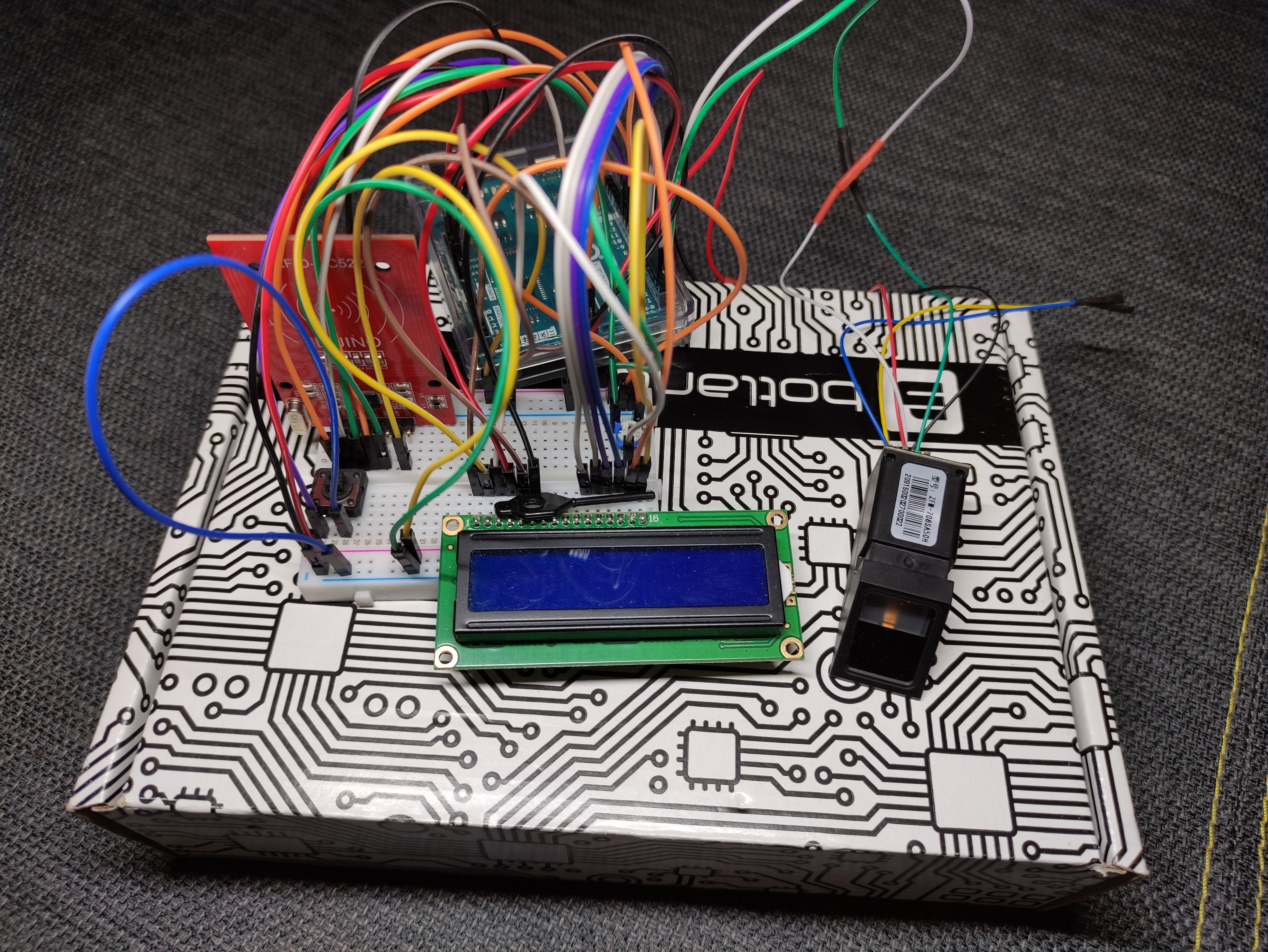
Wiring, despite how it looks is very simple, and explained below. Most important notes:
- Most of RC522 modules are powered with 3, 3 V supply, and are very sensitive, so make ABSOLUTELY SURE, you are connecting it with correct voltage, Leonardo has dedicated pin, prividing 3, 3 V
- On your RC522 you leave 2 pins not connected to anything - IRQ and RST
- You connect your LCD's LED anode to Arduino digital pin, instead of 5 V supply
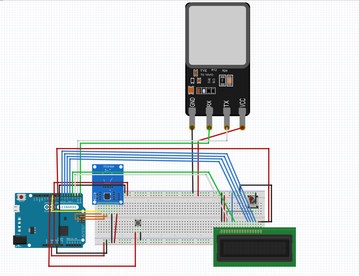
Arduino Leonardo pinout for this project:
- D0 (RX) - TD pin of Z70
- D1 (TX) - RD pin of Z70
- D2 - RS pin of LCD
- D3 - Enable pin of LCD
- D4-D7 - Data 4-7 pins of LCD
- D8 - LCD anode
- D9 - blank
- D10 - SDA/NSS pin of RC522
- D11 - log out/LCD on button
- ICSP SCK (9) - SCK pin of RC522
- ICSP MOSI (10) - MOSI pin of RC522
- ICSP MISO (11) - MISO pin of RC522
- 3, 3 V out - supply for RC522
- 5 V out - supply for LCD, button and Z70 sensor
CODE -before you begin
Before anything, you need to add 5 libraries to your Arduino IDE (if you don't have them yet):
- Keyboard.h
- SPI.h
- MFRC522.h
- LiquidCrystal.h
- Adafruit_Fingerprint.h
You do this in libraries manager, accessed by Ctrl+Shift+I. Then copy this project code to your IDE.
Next you want to go to line 128 and comment out logOut() function callout (so you don't log out of your system during debugging), and do the same with passwd() function callout in line 190.
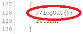
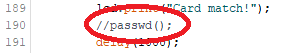
Just don't forget to uncomment these, when you're finished, or you won't be able to log in or out!
Last thing is to set your password in code, so Arduino can write it down when logging in. You do that in line 23, changing password string variable.

CODE
So first thing to do is to determine your RFID card ID. To do that connect everything as shown below, and open this project's code in IDE. In line 184 you have commented out debug line, that dumps readed card ID to Serial monitor. Just uncomment that, upload to Arduino, open Serial monitor and move card close to reader.

Readed ID copy to "logCard" string variable in line 22.

If you use only RFID reader, comment out line 184, uncomment lines 128 and 190, upload code to Arduino, and you are done. If you're using fingerprint reader, only comment out line 184, and keep reading.
CODE - with Z70 fingerprint reader (or any, that is supported by Adafruit_Fingerprint library)
So now you need to save your finger(s) to Z70 memory. To do that open new project in IDE, and from File -> Examples -> Adafruit Fingerprint Sensor Library open "enroll" example. Upload it to Arduino, open Serial monitor, and do as it says. The example is quite self-explanatory, and will walk you through adding as many fingerprint scans as you like, assigning them to IDs from 1 to 999.
After you added your finger, go back to this project's code. Now you have two options:
- leave it as it is, every finger you saved to Z70's memory will unlock your PC
- make some changes in code, to let only particular finger IDs unlock PC
CODE - unlock PC with only specific finger
Okay, so you let your sister, mother, father, grandma and dog save their fingers to sensor, and don't want to empty whole it's memory, you also want only your finger to be able to unlock the PC. Great, so you need to dig some more in the code. In lines 47 and 48 (in FingerID() function) there are some more commented out debug options, you want to uncomment. These dump ID of readed finger to Serial monitor. Pretty much like with RFID card ID, uncomment these, upload, place your finger, and read its ID from Serial monitor.

Now you go all the way down to switch, that starts in line 176. In there you have "case 0", that unlocks your PC with RFID and "default", that unlocks it with any finger in Z70's memory. What you want to do is add another case, with ID of your finger (read from Serial monitor), like "case 1:", copy contents of "default" to it, and empty out the "default".
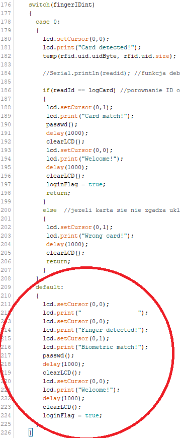
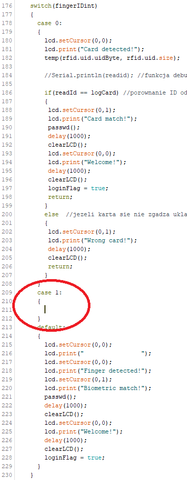
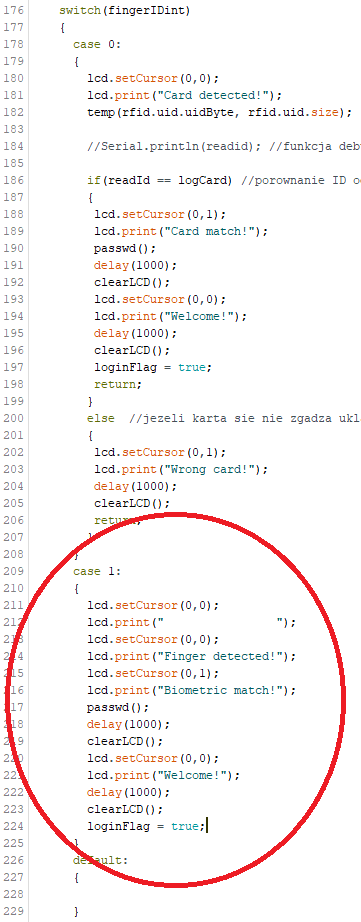
You can add as many new cases, as you want, with personalized LCD message, for every person's login, like "Hello mum!", "Hi dad!", "Get out you little piece of...
Anyway, now comment back out lines 47 and 48, and you are pretty much done with this project.
CODE - tweaks, tips, and do what you forgot to do, despite I reminded it many times
First of all - make sure lines 128 and 190 are UNCOMMENTED, and lines 47, 48, 184 are COMMENTED OUT!
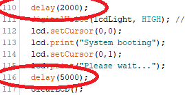
Now to less important tweaks. My PC boots up fairly long, so I added a 7 second delay before first loop starts. It is located in setup(), in lines 110 and 116. You can change it of course, if your system boots up longer or shorter. Keep in mind, it only logs you up to Windows 10, after your lock screen appears (if you place card/finger during boot, you have to click button and try again).
Another tweak. To save a bit the LCD and not drive me crazy with fingerprint scanner flashing LED the screen and Z70 turns off after 15 seconds. When that happen you can still unlock with RFID card, but to use finger, you need to press the button to activate sensor.
You can change how long it takes to turn them off, by tweaking if statement in line 147. To measure perfectly, you want to go to line 160, uncomment it, and just look how high gets the number after desired time (each iteration number on screen will increment, so for me it is 90 after 15 seconds). When you have your number, you just paste it in line 147 instead of 90, and comment back out line 160.


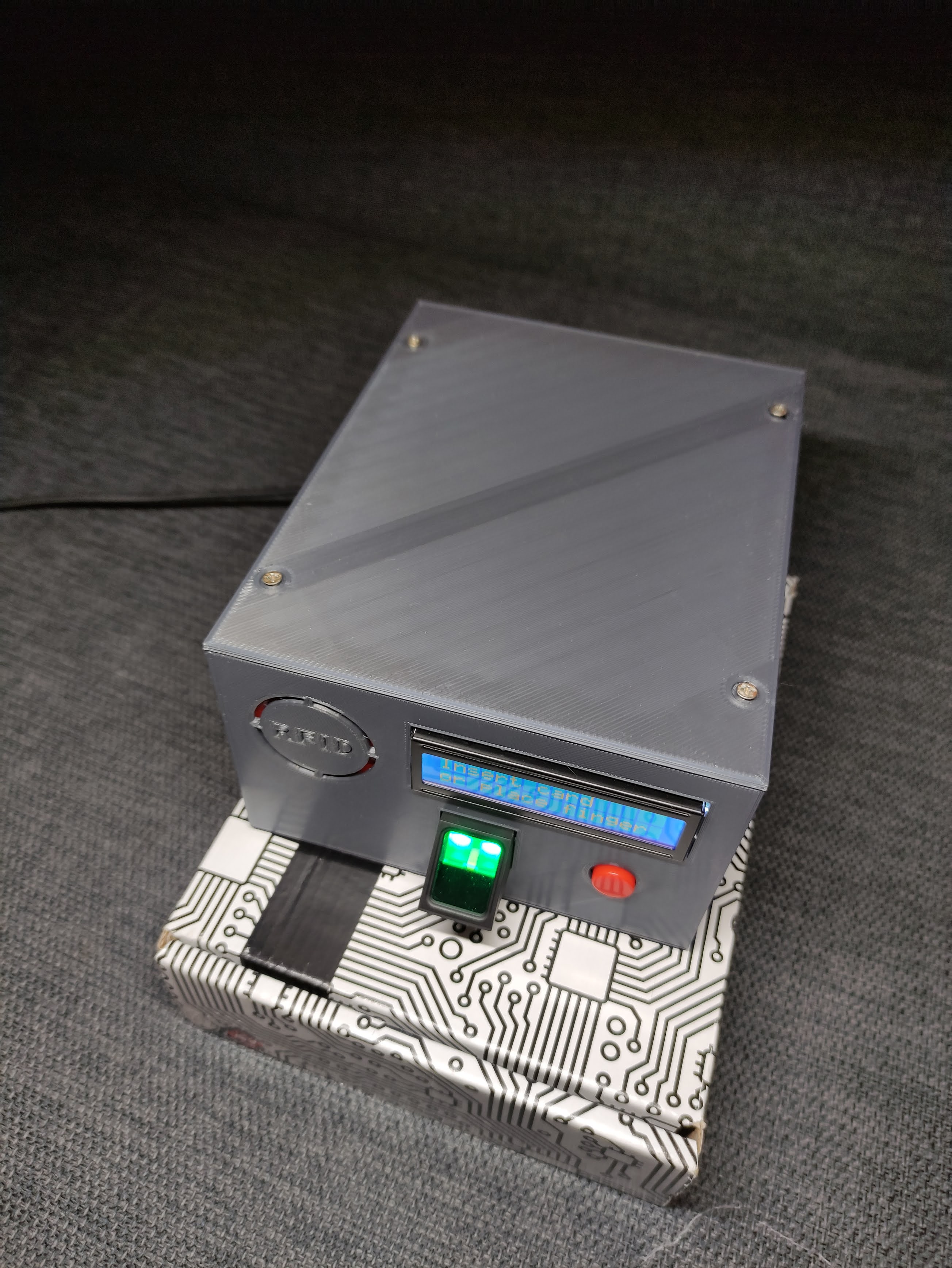
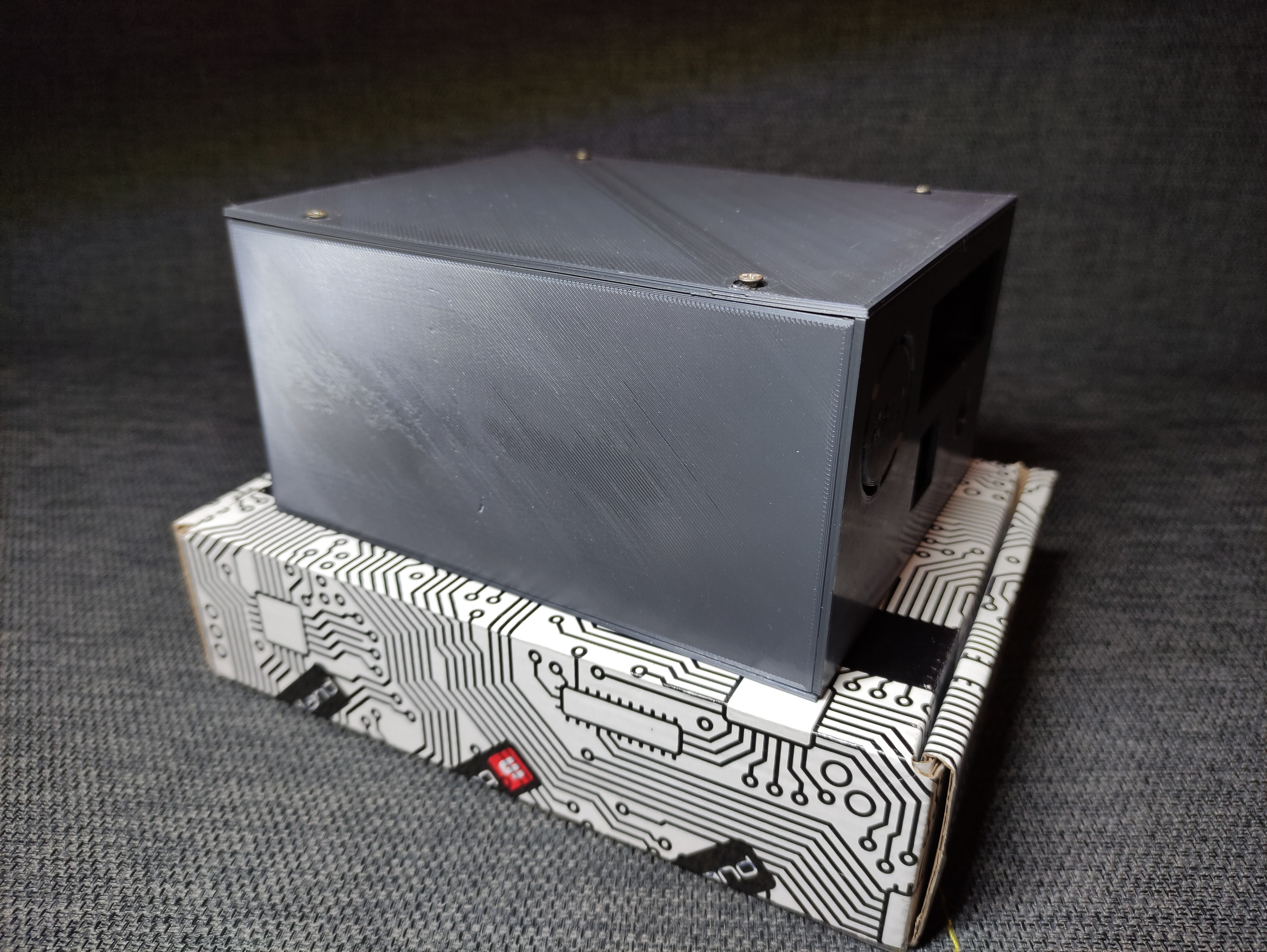
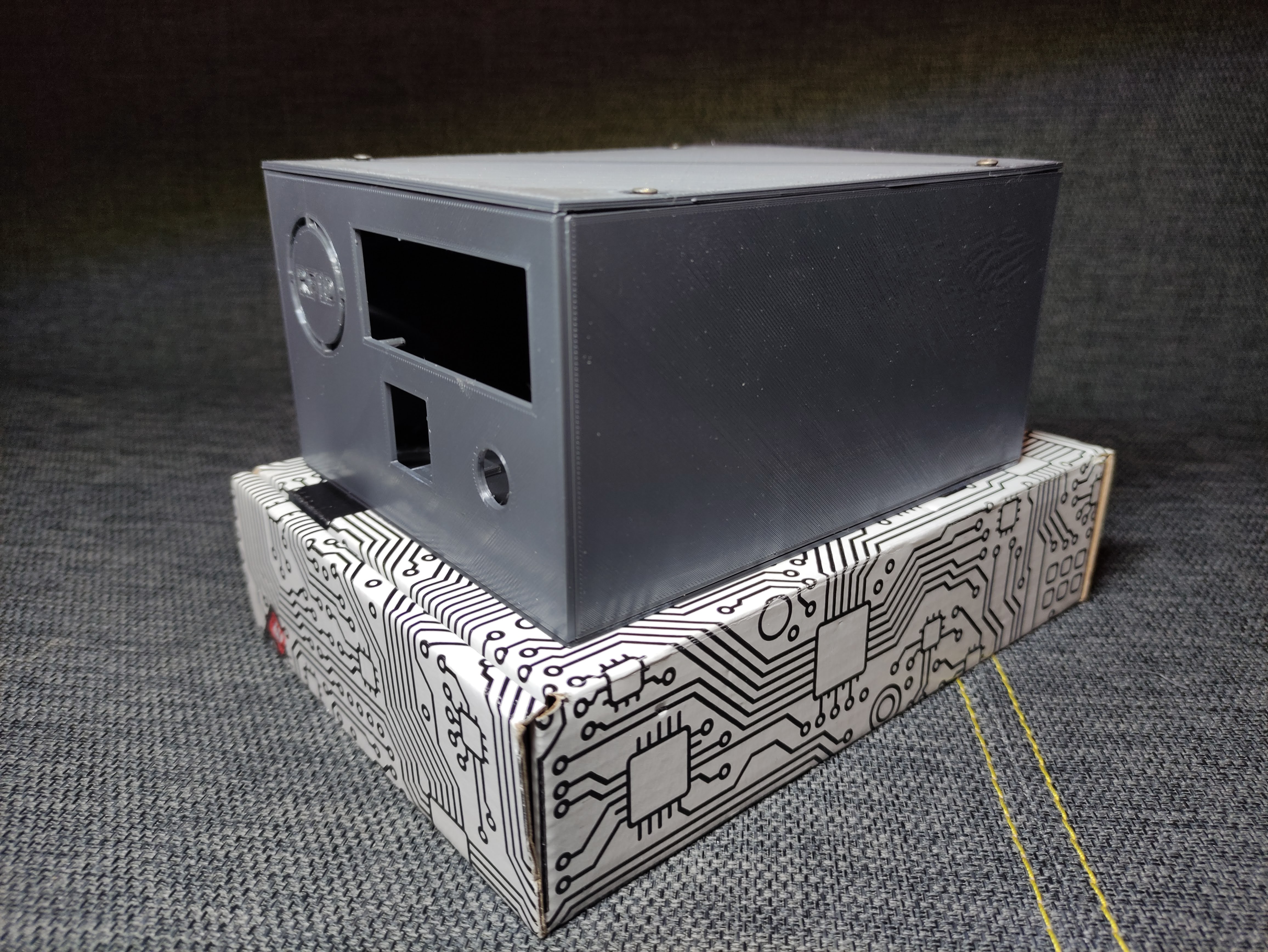
3D PRINTED CASE
Here is a link to Thingiverse, containing STLs to print my case. To assemble it you need cyanoacrylate glue (like super glue) and four tiny furniture screws. And a lot of patience, it takes FOREVER to print, and then cure the glue. Also you want to put the glue only INSIDE of the case, becouse CA glue leaves nasty white thing on PLA.
https://www.thingiverse.com/thing:4677132
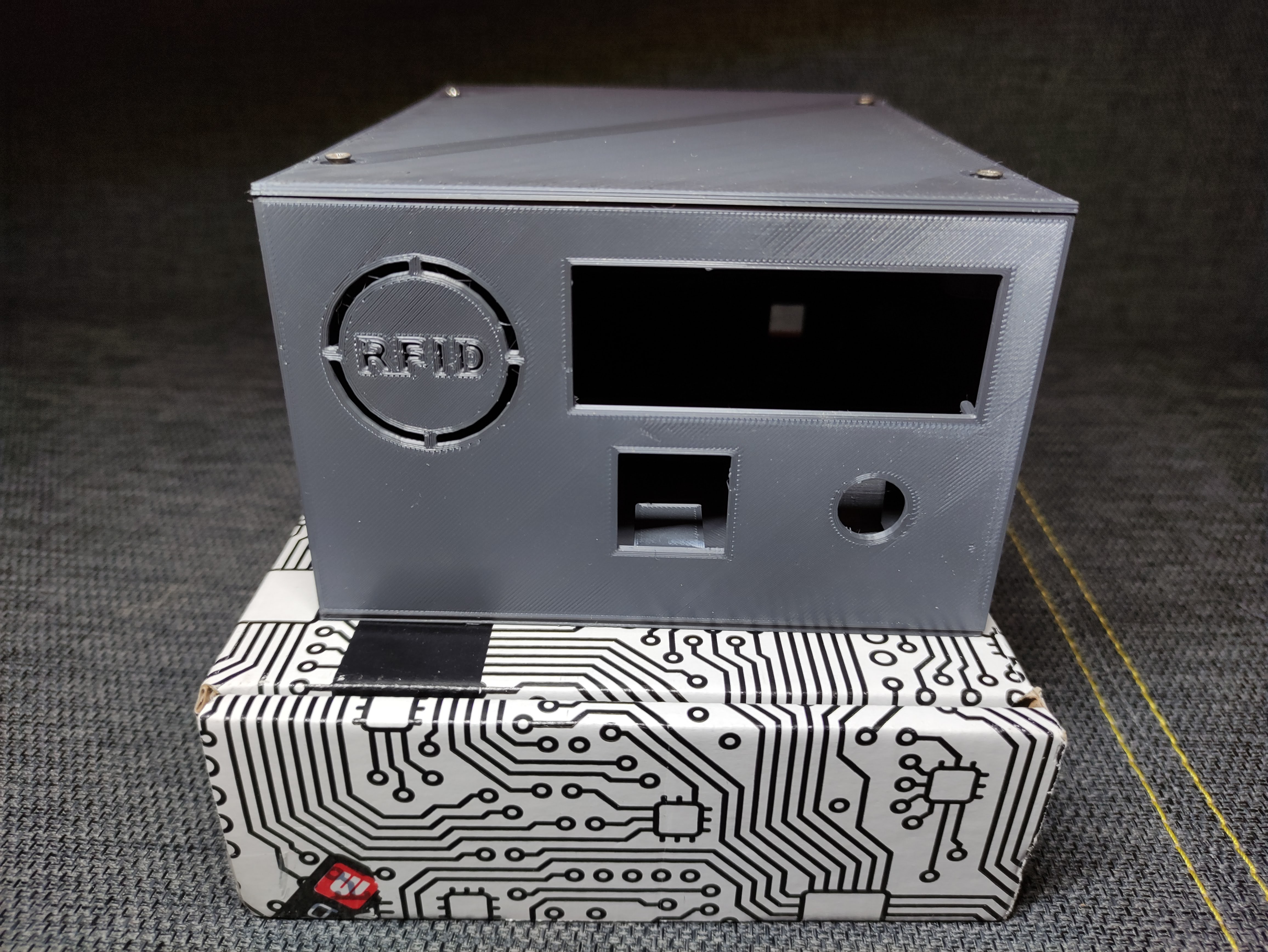
I printed it on Tevo Tarantula Pro, on glass heated bed. Here are parameters (they are also on Thingiverse):
Front, front elements (pins and fingerprint/button slots) and top:
Extruder/Bed temperatures 200/50; layer 0.2 mm; infill 10% Honeycomb; Ironing off; speed 60 mm/s; Z hop on
Bottom, back, sides:
Extruder/Bed temperatures 200/50; layer 0.3 mm; infill 10% Honeycomb; Ironing off; speed 60 mm/s; Z hop on
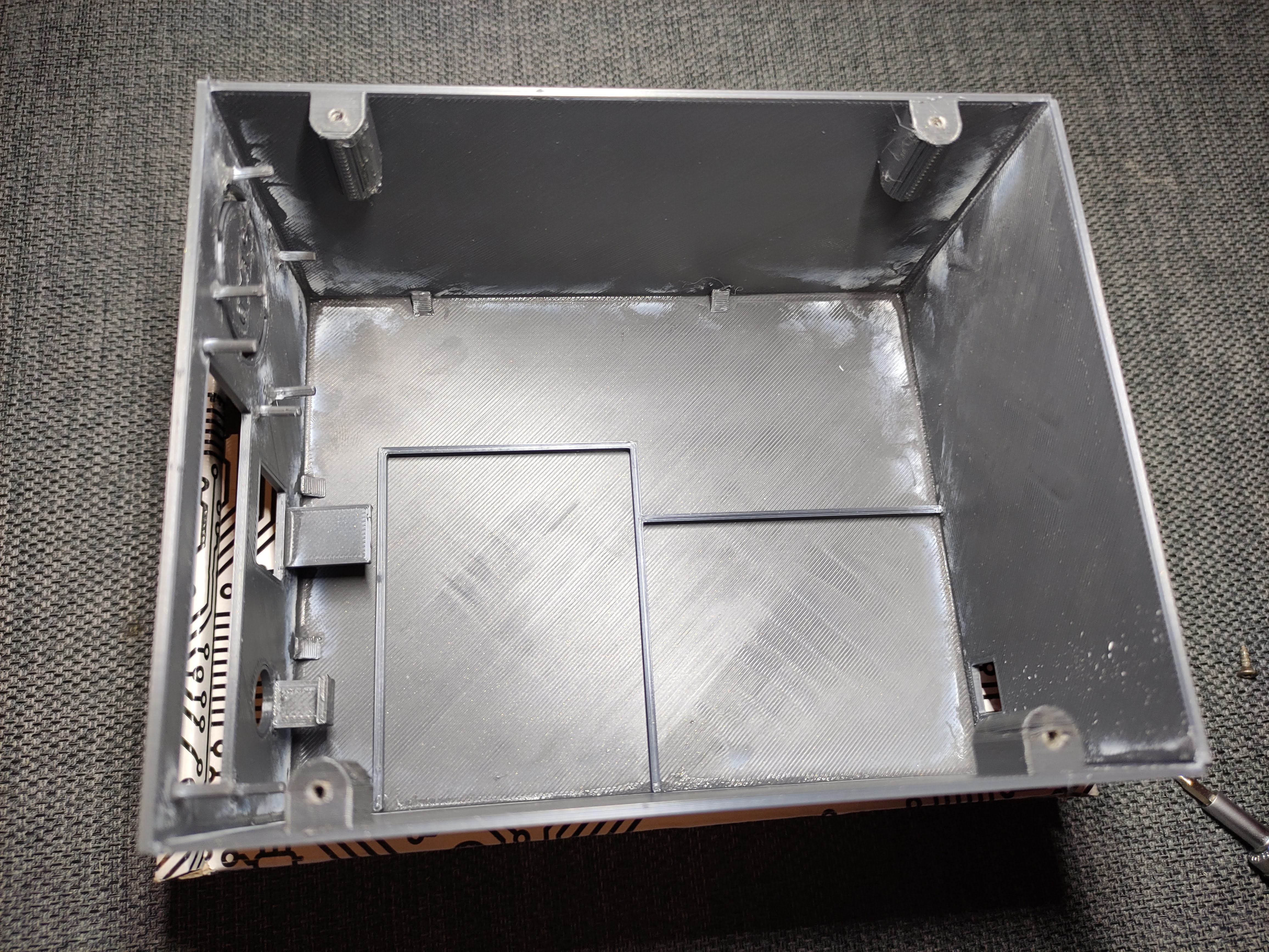
It took me over 14 hours to print it all.
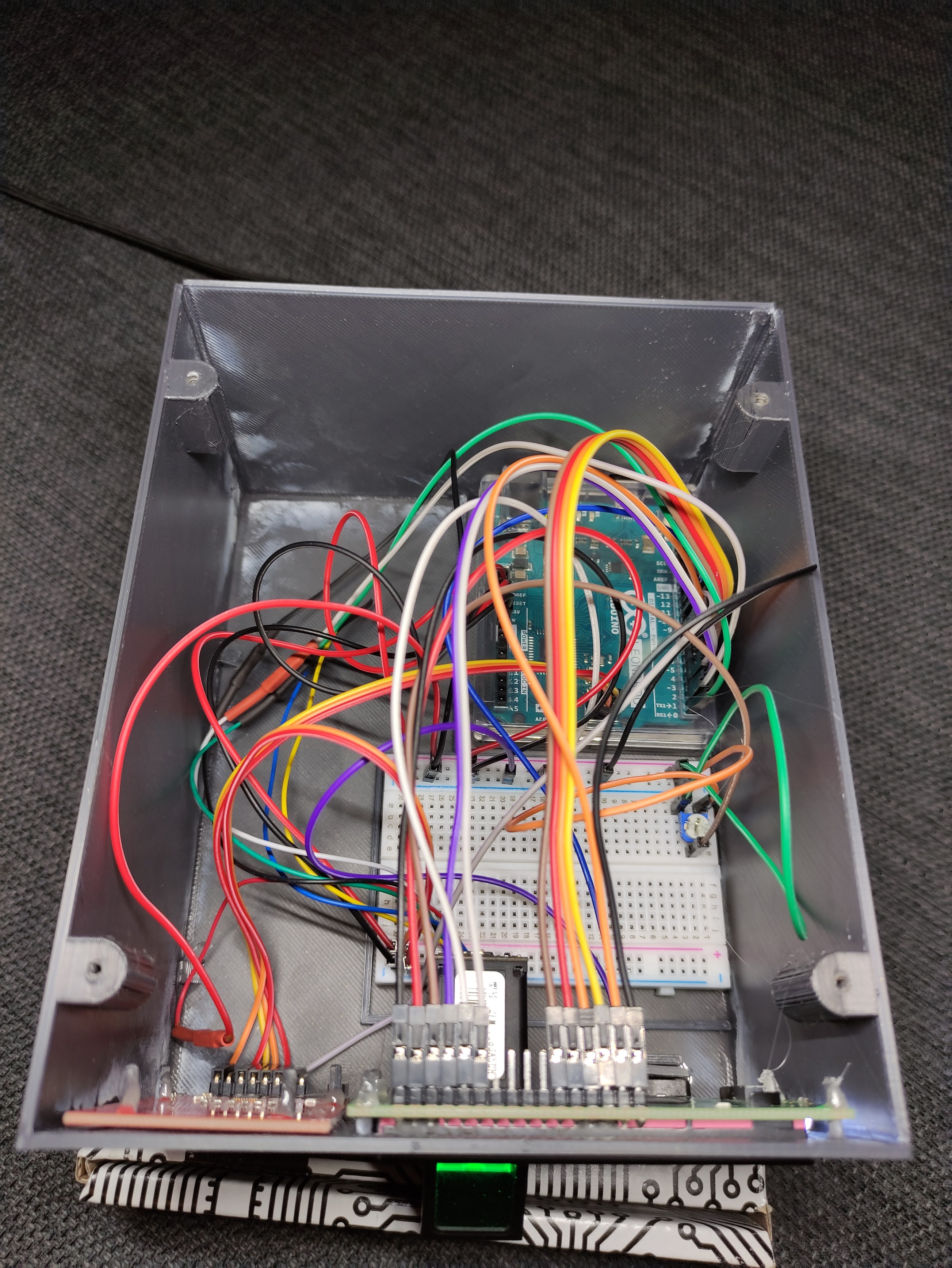
Also after you put everything together, it won't hurt to place a drop of hot glue on each pin behind LCD, RFID reader and button, to hold them in place. You can lock fingerprint sensor in place with zip tie or also hot glue.
So that's it, thank you for reading this and I hope you manage to make it on your own!
🛠️ เจาะลึกเบื้องหลังการทำงาน (Deep Dive / Technical Analysis)
Typing a 24-character heavy alphanumeric password onto a Windows PC 50 times a day is incredibly tedious. The PC Log In/Out Interface completely destroys the manual keyboard interaction natively! Utilizing an Arduino Pro Micro (ATmega32U4 chip), the board brutally disguises itself specifically as an authentic USB Gaming Keyboard! Connected to an R307 Biometric Fingerprint Scanner OR an MFRC522 RFID Array, the second your fingerprint perfectly matches the complex optical ridge-template stored physically on the sensor, the Arduino violently blasts the literal keystrokes MyC0mpl3xP@ssw0rd! directly over the USB dataline instantly unlocking the workstation flawlessly!
The Native USB-Peripheral Paradigm (Keyboard.h)
An Arduino Uno completely fails at this project natively because its USB architecture is an inflexible CH340 Serial Converter. The ATmega32U4 has native raw access to the USB Bus!
- The
<Keyboard.h>library commands the silicon to directly send Keypress Interrupts identical to a physical $150 Corsair Keyboard! - The Arduino waits patiently in a deep sleep for the Biometric Serial interruption.
- Upon positive ID confirmation, it physically executes
Keyboard.print("Password123")followed aggressively byKeyboard.write(KEY_RETURN)(Enter Key!).
#include <Keyboard.h>
#include <Adafruit_Fingerprint.h>

// Massive Biometric Initialization Serial Matrix
SoftwareSerial mySerial(2, 3);
Adafruit_Fingerprint finger = Adafruit_Fingerprint(&mySerial);

void loop() {
  int fingerprintID = getFingerprintID(); // Check the heavy optical sensor autonomously!

  if (fingerprintID == 1) {
    // FINGERPRINT #1 IS AN ABSOLUTE MATCH! (The Administrator!)
    Keyboard.begin();
    delay(500); // Wait for Windows to actually focus the login box natively!

    Keyboard.print("SuperSecureAdminPass99!"); // Violently type out the entire string instantly!
    delay(100);
    Keyboard.press(KEY_RETURN); // SMASH ENTER!
    delay(100);
    Keyboard.releaseAll(); // Cleanly release the physical key interrupts!

    Keyboard.end(); // Sever the spoofing pipeline!
    delay(5000); // 5-Second absolute lockout to prevent accidental double-execution!
  }
}
Incorporating The R307 Optical Biometric Sensor
The Arduino does not analyze the fingerprint image; it does not have the processing power!
- The R307 sensor holds a massive optical camera and its own heavy embedded processor!
- Enrollment Phase: You upload an "Enroll" sketch to the Arduino. You place your finger natively on the glass twice. The sensor processor generates a horrifyingly complex mathematical hash map of your minutiae ridges and permanently burns it directly into its own internal Flash memory!
- Matching Phase: During daily use, the sensor simply takes a picture, runs the math, and shoots a simple Serial command backward to the Arduino:
MATCH: ID 1!
Authentication Cybersecurity Hardware
- Arduino Pro Micro / Arduino Leonardo (The ATmega32U4 is 100% absolutely mandatory for the
Keyboard.hHID protocol!). - R307 / AS608 Optical Fingerprint Scanner (Or an MFRC522 RFID module for encrypted proximity cards!).
- Logic Level Converter (CRITICAL: The R307 TX/RX explicit pins communicate strictly at
3.3V Logic. If you ram a 5V Pro Micro transmission into it directly, you will violently incinerate the expensive biometric micro-processor!). - USB Data Cable (MUST explicitly be a data synchronization cable! A cheap charge-only cable will literally provide power but absolutely fail to enumerate the HID spoofing device in Windows!).