This is a really simple easy to assemble digital clock created using the RTC DS1307 IC. With an LCD display. It simply displays the time on a 4 digit seven segment display. The code can also be easily tweaked to give it additional functionality like an alarm, all you need is a little imagination and ingenuity. This project was made just as a stepping stone to better and more complicated things, plus I wanted to make something cool looking to put up for display in my room.
So enough being said, I will include every little detail in this post including the problems I ran into while soldering it onto the PCB and how I resolved these said issues.
STEP 1: Components
RTC Module
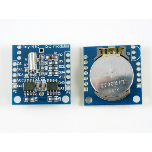
The DS1307 chip is really awesome since it has the ability to keep track of the time even during power off time. Its easy to interface with the Arduino and there are a lot of libraries available for working with this module. The RTC interfaces with the Arduino through the I2C protocol. Not to worry about the details of the protocol the Pins A4 and A5 on the Arduino nano are used for I2C communication.
- SDA - A4
- SCL - A5
We wont be needing the DS pin for this project.
The only downside is that its not as accurate as we would like it to be. The chip is very susceptible to time drifting and it very easily drifts away from the actual time depending on the temperature.
NOTE- Make sure you connect the GND and Vcc pins correctly. The Vcc is placed (in the module) before the GND pin. I connected mine in the reverse polarity several times and it gets very hot very fast. So if you are vary of connecting the polarity in the reverse just touch the coin cell when switching it ON and quickly switch it OFF if you sense it getting hot.
Shift Register (74HC595)
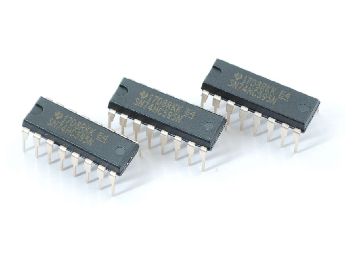
- The Shift register 74HC595 was the chip that made it possible thanks to the technique of multiplexing. Beginners don't be afraid of this scary looking term its fun and you will be glad you learnt it.
- The 595 has 16 pins and we will be using two shift registers to interact with the 4 digit 7 segment display.
- The first shift register is used for lighting up the segments and the second shift register is used for selecting which digit I will be lighting up.
- Thanks to the technique of multiplexing the switching between digits is done so fast. It seems like all the digits are being displayed at the same time.
NOTE: These chips are quite reliable but I happened to get several faulty ones. In some chips the Q0 and Q1 were not working. Some had the Q3 grounded internally (construction mistake). The ones I have in my project now are also not entirely perfect. One of them has its Q7 faulty, so when I was working with them I had to make sure my connections were exact, and when they still weren't working I had check the pins using the continuity function of my multi meter. All in all I don't complain, since it's all means to learn to over small obstacles while doing a project.
4 Digit seven segment display
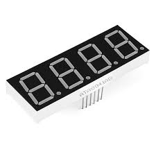
I have used a generic 4 digit segment (Common Anode). It has 12 pins the numbering starts from bottom left and ends at the top left pin. Each segment is capable of displaying digit and a decimal point. So since I don't have the cool looking colon typical to digital clocks I had to make do with the decimal point of the second digit. These are great displays when your primary objective is to display numbers.
NOTE: These can be quite tricky to work for beginners, since the segments a-g are not in the same line. Be careful and do not connect them the 5v supply without any current limiting resistor.
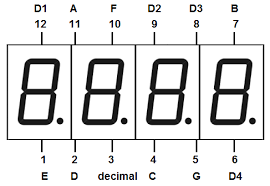
I have included a schematic for this and its pretty self explanatory.
The Schematic doesn't have the same type of display as I used in the project so here is the pin connections from the shift register to the segment.
Segment Pin no. on the display Shift register pin
A 11 15
B 7 1
C 4 2
D 2 3
E 1 4
F 10 5
G 5 6
Decimal 3 7
D1 12 15(2nd 595)
D2 9 1(2nd 595)
D3 8 2(2nd 595)
D4 6 3(2nd 595)
This project is cheap and easy to make but requires a little patience and perseverance (that is if your are willing to go the extra mile to solder it on the PCB). If you just wanna try it out for fun it hardly takes 2 hours.
Please give your feedback as to how I can improve this and If there is anything have not mentioned clearly in the post.
🛠️ เจาะลึกเบื้องหลังการทำงาน (Deep Dive / Technical Analysis)
The Arduino has a glaring flaw: every time you unplug it or press the reset button, all its internal timers return to zero. It literally has amnesia. The Real-Time Clock (RTC) project fixes this by offloading the task of remembering what year it is to a specialized I2C chip that has its own backup battery.
How the DS3231 Functions
The DS3231 Module is the absolute gold standard for hobbyist clocks. (The older DS1307 drifts out of sync by minutes every month; the DS3231 is temperature compensated and stays accurate within a minute per year!).
- The Watch Battery: A small CR2032 coin cell battery sits on the back of the module. Even if you throw the module in a drawer for 5 years with no Arduino attached, it continues counting seconds!
- The I2C Bus: You connect the module to the Arduino via
SDA (A4)andSCL (A5)pins, plus 5V and GND. - Using the
<RTClib.h>library, you initialize the bus.
Flashing the Current Time
You must "Set" the watch once before you can read it.
- The Set Function: You run a script containing
rtc.adjust(DateTime(2026, 10, 24, 15, 30, 0));. You upload it. The chip is now tracking October 24, 2026, 3:30 PM. - The Read Function: You delete the "Set" line from the code so it never resets again.
- Inside the main
loop(), you type:DateTime now = rtc.now();Serial.print(now.hour(), DEC);Serial.print(':');Serial.println(now.minute(), DEC);
Now, you can unplug the Arduino, plug it back in, and it will instantly print the correct, mathematically perfect time!
Required System Build
- Arduino Uno/Nano.
- DS3231 Real-Time Clock Module (Ensure it includes the CR2032 battery).
- Any Display (LCD/OLED): Optional, if you want it off the Serial Monitor.