Hello.
In this Project, you will create a button press LED. When The button is pressed, the LED will turn on. In the Tips and Tricks after the trouble shooting page, you may add a off button to turn the LED off. Don't worry, the full code will be provided. Finally, don't forget to check out my website and YouTube channel!
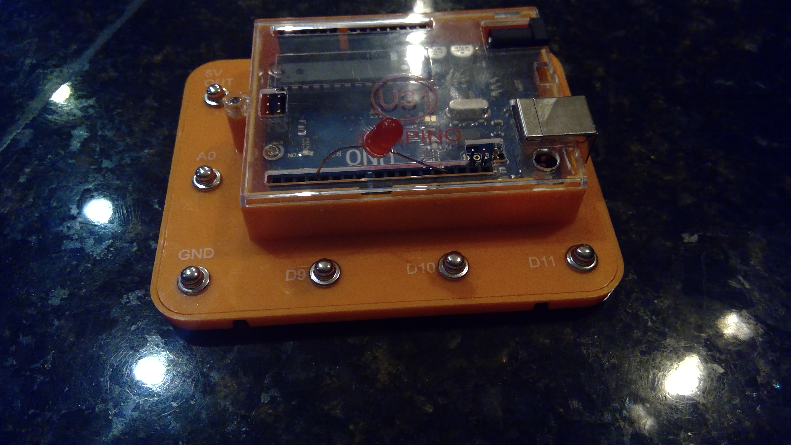
Attaching The LED To The Uno
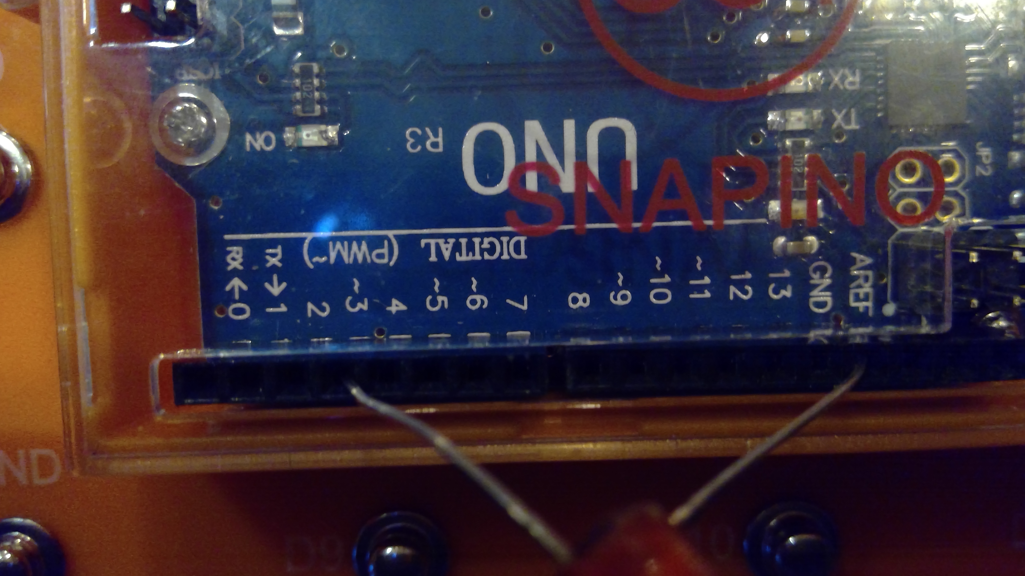
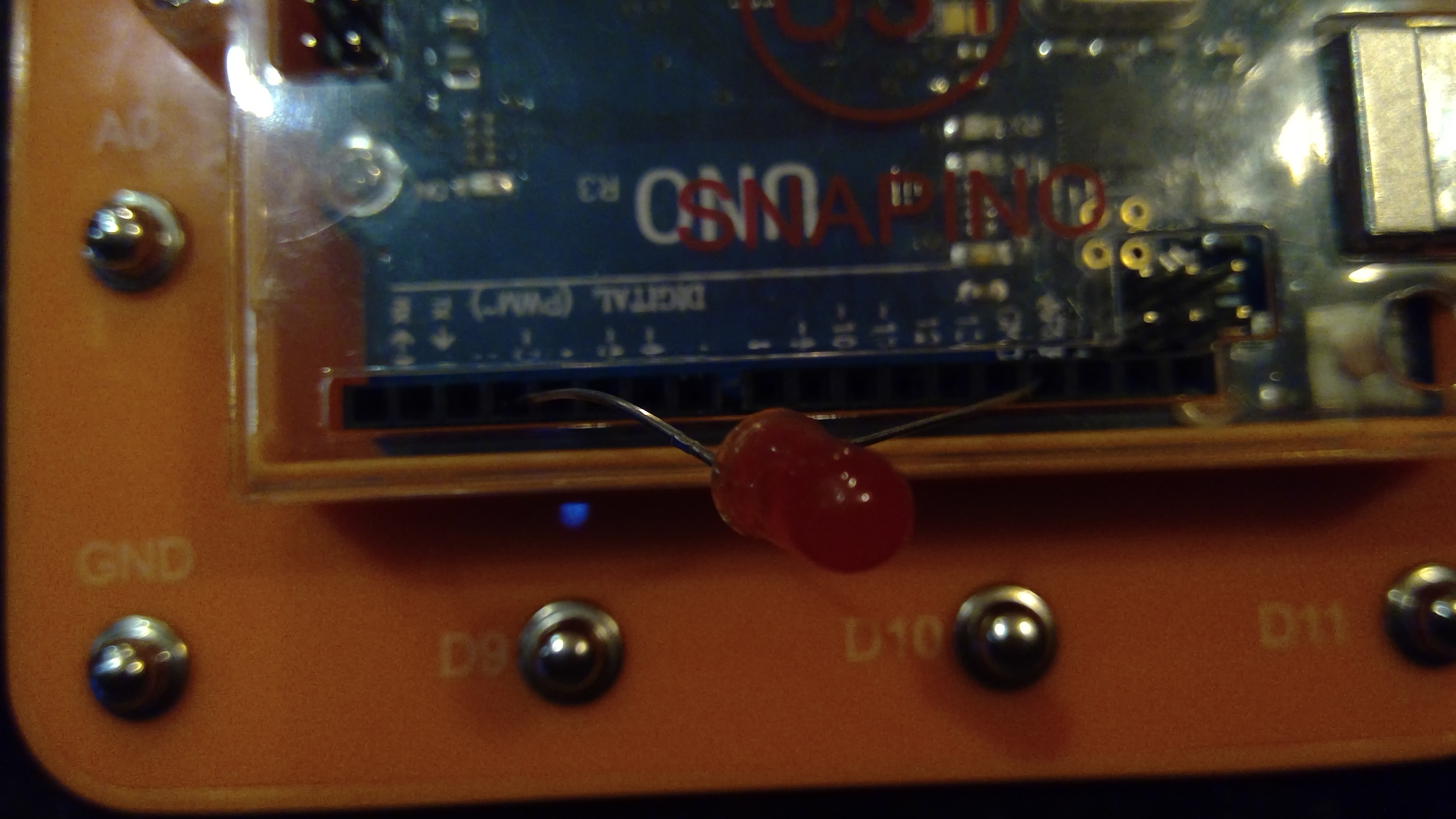
Lets start with adding the LED. The LED will be attached to pin3. Don't forget that the LED is on the digital side, not the Analog. An image is provided below.
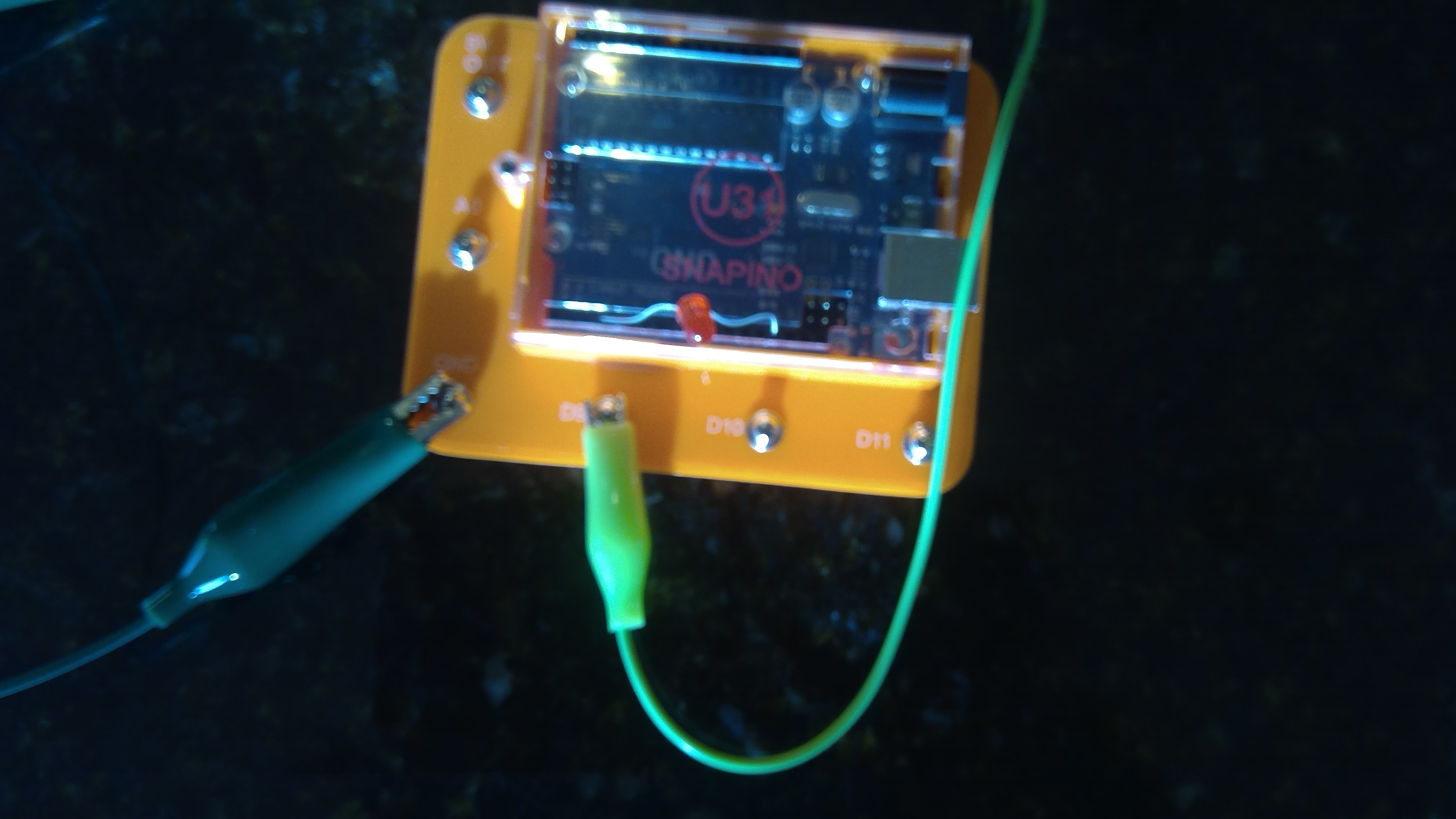
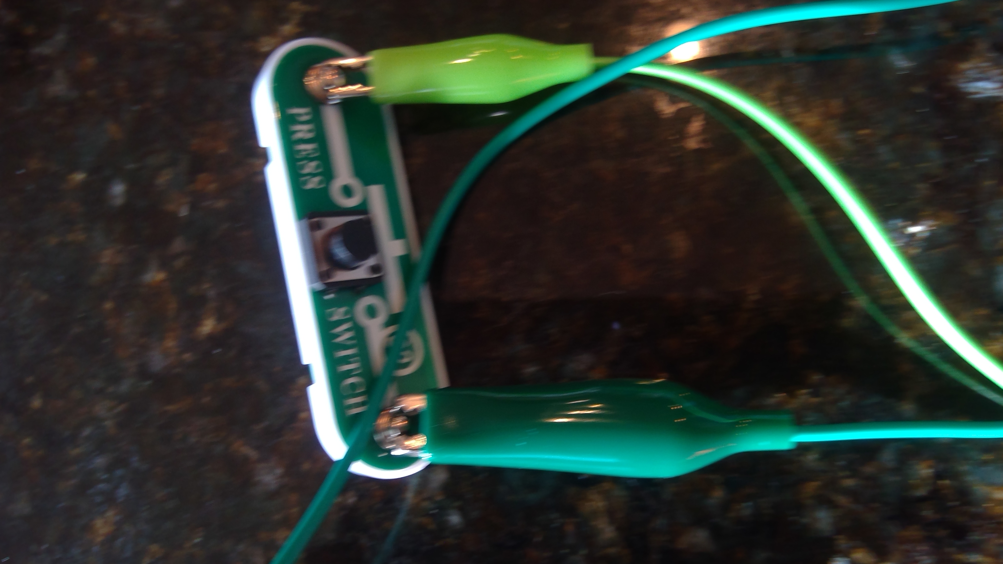
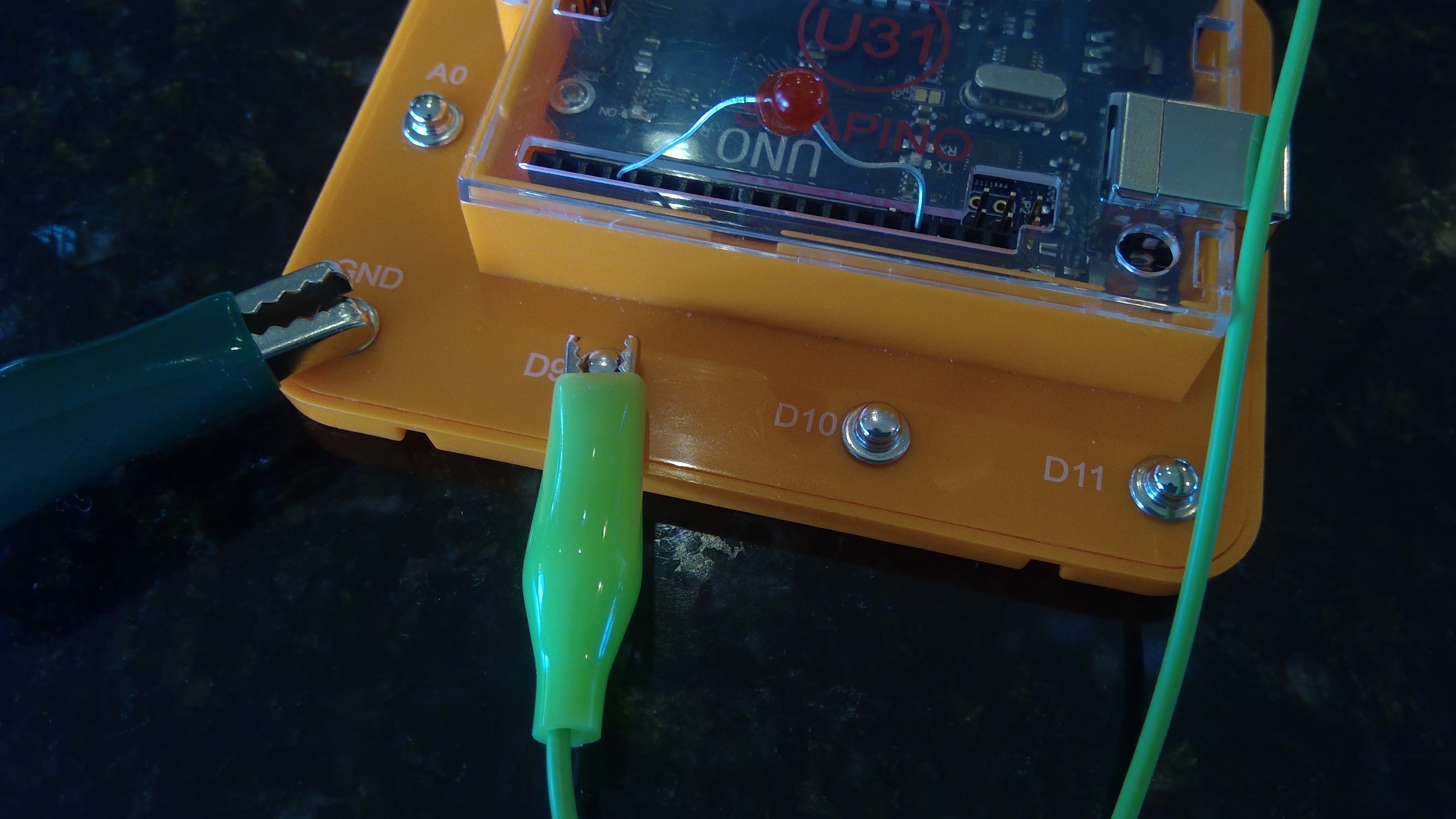
Adding The Button To The Uno
Now that we have the LED connected to the Snapino, we may add the button to activate the LED. Add the button to D9 and make sure that the LED and button are connected to ground(GND). You may use a different button, but ensure it is SPST(Single Pole Single Throw).

Writing the CODE
Finally lets write the code. Don't you worry! You ain't writing it all with the indents and curly brackets and brackets and quotation marks! The code is provided below. Make sure you copy and paste it in your IDE. If you do not have the Arduino IDE, see arduino.cc
Enter this code into your IDE:
void setup() {
//button1
pinMode(9, INPUT);
//led1
pinMode(3, OUTPUT);
}
void loop() {
if(digitalRead(9)==LOW){
digitalWrite(3, HIGH);
}
}
____________________________________-______-_______--
Don't forget that DO NOT TYPE void setup() { and void loop() {.
____________________________________-______-_______--
Troubleshooting
If you code does not work, try the following:
Make sure Your Button is connected to ground
Make sure your LED is connected to ground
Make sure you have not used hot glue on your button and it works
Make sure LED is not burnt out or does not work
Try running the Snapino test program to ensure the Snapino UNO is working properly
Tips and Tricks
If you would like to go farther, try one of these tricks:
-- You could add a off button to turn the LED off using this code:
void setup() {
//button1
pinMode(7, INPUT);
//button2
pinMode(8, INPUT);
//led1
pinMode(3, OUTPUT);
}
void loop() {
if(digitalRead(7)==LOW){
digitalWrite(3, HIGH);
}
if(digitalRead(8)==LOW){
digitalWrite(3, LOW);
}
}
The LED would be connected to pin 3 The button to turn it on will be on pin 7 and your off button will be on pin 8.
-- Change the code so the led starts on and you press the button to turn it off using this code:
void setup() {
//button1
pinMode(10, INPUT);
//led1
pinMode(3, OUTPUT);
}
void loop() {
if(digitalRead(10)==LOW){
digitalWrite(3, LOW);
}
}
_______________-___-_-_-__-_-_____-_____-______-_____-_
Successful


That is The end. You just made a code or program to have it where when you press a button, the LED turns on! Great job! Have a good day with your new code! Don't forget to save it on your computer so you can use it again.
Thank you.
🛠️ เจาะลึกเบื้องหลังการทำงาน (Deep Dive / Technical Analysis)
Before you can build robots or smart homes, you must master the fundamental building block of electronics: the LED Circuit. This project teaches you how to control a digital output and protect your components from damage.
Why use a Resistor?
The most important lesson in this project is Current Limiting. An LED is a diode with very little internal resistance. If you connect it directly to the Arduino's 5V pin, it will draw too much current and burn out instantly.
- The Solution: We place a 220-ohm resistor in series with the LED to limit the current to a safe level (around 20mA).
The Hardware
- Arduino Uno: Used here as a 5V power source.
- LED (any color): The output device.
- 220-ohm Resistor: The protector.
- Breadboard and Jumper Wires: For clean, solderless connections.
What You'll Learn
By building this, you'll understand polarities (the Anode + and Cathode - of an LED) and the basic layout of a breadboard. It's the simplest project there is, but it's the foundation for every blinking light, indicator, and screen in the world.