This project is basically what it sounds like - a smart outlet. This smart outlet can apply to any device that has a plug FOR 120V only! (Targeted mainly at lamps using low amps.) This outlet is an outlet controlled by a 1-channel relay. This project also uses an RTC (real time clock) to determine what time it is and, based on the 24 hr clock, it will either turn on or off (depending on the time) because it actually has predetermined times to turn on and then to turn off. Also, another thing is that this will have a plug coming out of it that has to be plugged into a wall socket!
Link to the library: http://www.rinkydinkelectronics.com/library.php?id=73
IMPORTANT SAFETY INFORMATION!! PLEASE READ!
1) Use a Grounded Cord and Interrupt the Hot Wire
As can be seen in the pictures below, a 3-prong plug is used. The hot (black) wire from the line is connected to the common terminal of the relay module. The normally open (NO) output of the relay is then connected to the brass screw of the outlet. The white wire (neutral) connects to the silver screw and the green (ground) connects to the green screw of the outlet.
2) Use a Relay Module
A single-channel relay module from Elegoo was used to switch the hot wire. This module is identical to the Keyes SR1y module (http://www.techydiy.org/keyes-sr1y-relay-module) and contains a flyback diode connected to the control input (for back EMF), a transistor to control the relay coil and a series resistor to limit the current into the transistor. As the relay is only rated up to 10A, either limit the load connected to the outlet, or use a fuse in line with the hot wire. If possible, a single channel relay with an optocoupler would provide additional isolation for the Arduino.
3) Physical Separation
Make sure to mount the relay module in the plastic housing away from the high voltage wires ensuring that the solder side of the relay module faces the plastic housing so that low voltage wiring does not inadvertently come into contact with high voltage wiring if the unit is subjected to shock or vibration.
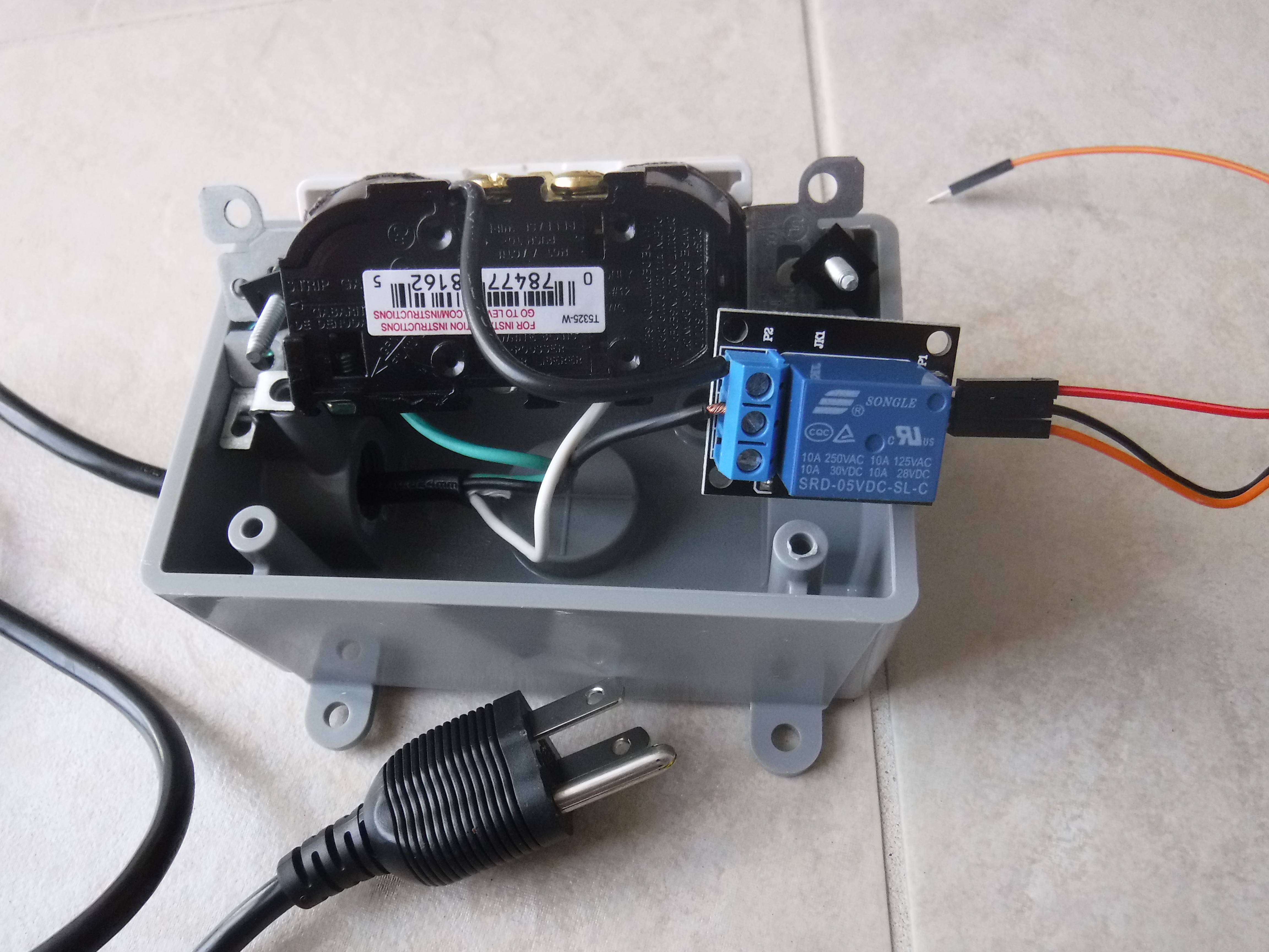
Image of the wiring on the inside of the smart plug (yours should look like this).
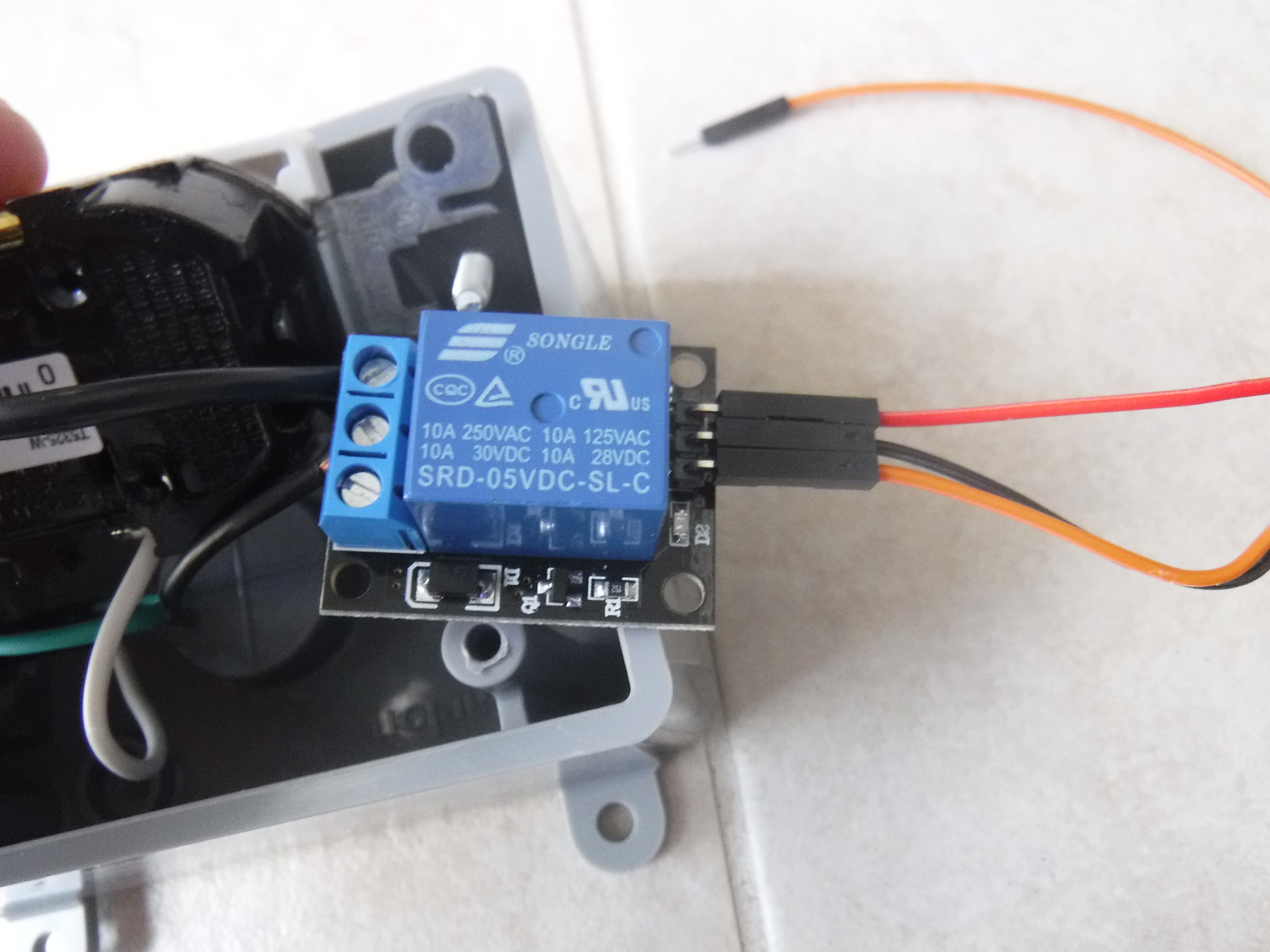
Close-up image of the relay module.
🛠️ เจาะลึกเบื้องหลังการทำงาน (Deep Dive / Technical Analysis)
A bare Arduino blinking an LED on a desk is harmless. Taking an ESP8266, encasing it into a totally enclosed plastic wall box, and commanding it to physically intercept and switch 120 Volts / 15 Amps of terrifying AC Wall Power via Wi-Fi elevates engineering into extremely dangerous commercial territory. The IoT Smart Plug controls massive appliances (Space Heaters, Air Conditioners) using pure HTTP/MQTT packets!
Enclosed Architecture Physics
When you build a device that plugs straight into a wall, you can't have a massive USB cable dangling out to power the tiny 3.3V Wi-Fi chip.
- The Smart Plug requires a deeply specialized, microscopic AC-to-DC Switch Mode Power Supply Module (SMPS) e.g., HLK-PM01.
- This terrifying little module solders directly to the
120V AClive wires and outputs a mathematically stable, flawlessly isolated5V DClogic stream specifically to power the ESP8266! - The Current Intercept: The AC
Livewire is spliced completely in half. It runs straight through an enclosed 5V Electromechanical Relay Module (e.g., SRD-05VDC-SL-C). - The ESP8266 simply sets its Digital Pin to
HIGH! The relay loudly clicks, the magnetic coil engages the metal armature, and the 120V wall current violently rushes out into the plugged-in Heater Appliance!
Overriding Cloud Control LOCALLY
If the Smart Plug is running a blender, and the Internet goes down during a hurricane, the user must still be able to turn the blender off!
- The design features a physical, local Tactile Push Button (Often a slick TTP223 Capacitive Touch Sensor under the plastic housing!).
- The Arduino code executes critical "State Toggle" redundancy logic!
// The loop must check BOTH the Wi-Fi MQTT packet AND the Local Hardware array!
if (digitalRead(LocalTouchSensor) == HIGH || mqttCommand == "TOGGLE") {
  relayState = !relayState; // Physically invert the hardware state!
  digitalWrite(RelayPin, relayState);
  delay(300); // Massive Debounce block so the touch sensor doesn't flicker!
}
Advanced Wall Requisites
- ESP8266 NodeMCU or ESP-01S (ESP-01S is massively preferred here due to its microscopic size, fitting entirely inside the wall plug!).
- Massive 5V Optically Isolated Relay Module (10-Amp / 250V AC Rated Minimum!).
- HLK-PM01 5V AC/DC Power Supply Module.
- (DANGER: This project directly manipulates lethal 120V/240V Mains Power. Any loose wire or poorly insulated trace touching the 3V logic side will literally explode the Wi-Fi chip and catch the wall on fire! DO NOT attempt without advanced high-voltage theory capability).