Hello there!
This is the first project that I am uploading on my Project Hub page. In this project I have made a traffic-light with 3 LEDs and a buzzer. The buzzer has been used for giving the pedestrians an alert that cars are now on the move!. So when the green LED turns-on the buzzer will start to beep and as soon as the green LED turns-off the buzzer will also stop beeping. As many of you have probably noticed, one of the usages of this project is on streets intersection for people with vision disability.
Here are the things we need:
- ARDUINO-UNO R3
- USB 2.0 Cable Type A/B (for uploading the code)
- 3 colorful LEDs(Red, Yellow, Green)
- 3 Resistors(220 ohm)
- Buzzer
- Breadboard
- some jumper wires
So now let's make it!
Here are the schematics of how it works!
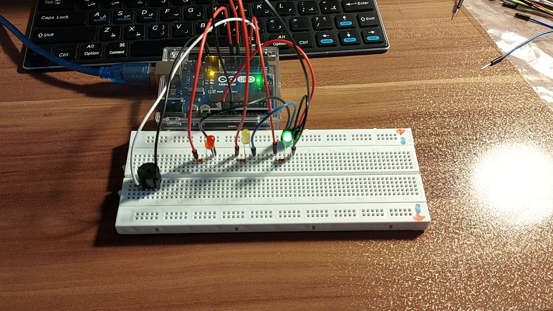
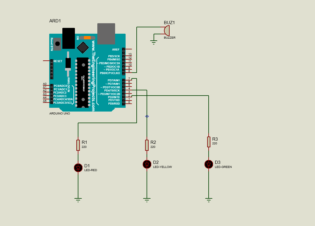
So, because we need 4 grounds in here and we only have 3 on the Arduino board, I made a common ground for all of them so that I don't get short of grounds!
As it is shown in the first picture, I have marked some positive and negative signs on my bread-board. Use a jumper wire and connect one side of it to the GND pin of your Arduino board and connect the other side to the negative mark on your bread-board. and from here connect the negative leg of your LEDs to the common ground of your bread-board. Oh by the way, you need to connect the positive leg of the LEDs to the 220 ohm resistor.
So now we are done with the electronic part! Now all you have to do is to upload the code.
const int ledRed= 7;// led is connected to pin 7
const int ledYellow=4;// led is connected to pin 4
const int ledGreen=2;// led is connected to pin 2
const int buzzer=8;// Buzzer is connected to pin 8
void setup() {
 pinMode(ledRed,OUTPUT); // the led is used as an output
 pinMode(ledYellow,OUTPUT);// the led is used as an output
 pinMode(ledGreen,OUTPUT);// the led is used as an output
 pinMode(buzzer,OUTPUT);// the Buzzer is used as an output
}
void loop() {
digitalWrite(ledRed,HIGH); // access the voltage to the ledRed
digitalWrite(ledYellow,LOW);//ledYellow is off
digitalWrite(ledGreen,LOW);//ledGreen is off
delay(5000); // wait for 5000ms
digitalWrite(ledRed,LOW); // ledR is off
digitalWrite(ledGreen,LOW);//ledG is off
digitalWrite(ledYellow,HIGH);// ledY is on
delay(2000); // wait for 2000ms
digitalWrite(ledRed,LOW);// ledR is off
digitalWrite(ledYellow,LOW);// ledY is off
digitalWrite(ledGreen,HIGH);// led green is on
delay(4000);// wait for 4000 ms
digitalWrite(buzzer,HIGH);// the buzzer is on
delay(500);// the buzzer will beep for 500ms
digitalWrite(buzzer,LOW);//the buzzer is off now
delay(500);// wait for 500ms
digitalWrite(buzzer,HIGH);// the buzzer is on again
delay(500);// wait for 500ms
digitalWrite(buzzer,LOW);// the buzzer is off now
}
🛠️ เจาะลึกเบื้องหลังการทำงาน (Deep Dive / Technical Analysis)
A traffic light normally controls cars based on timers. The Sound Alert Traffic Light controls human behavior based on acoustic physics. Most commonly deployed in elementary school classrooms or hospital hallways, it acts as a massive "Noise Enforcer." It uses an analog microphone to constantly sample the erratic waveform of room noise, utilizing moving-average mathematics to change an LED matrix from Green to Yellow, and finally, to blazing Red, triggering a buzzer if the room crosses the decibel threshold.
The Analog Peak-to-Peak Audio Physics
A microphone does not output a simple "0 to 1023" volume level. It outputs an incredibly complex, chaotic AC waveform swinging wildly across the 2.5V center bias.
- The MAX4466 or KY-037 Sound Sensor is connected to
A0. - The Sampling Window Trap: If you just run
analogRead(A0), you might accidentally read the exact millisecond the noise waveform crosses zero! The Arduino will think the screaming room is perfectly silent. - You must execute a tight, high-speed 50-millisecond Sampling Loop!
int signalMax = 0; int signalMin = 1023;
unsigned long startMillis= millis();
// Sample the chaos for 50 milliseconds!
while (millis() - startMillis < 50) {
  sample = analogRead(A0);
  if (sample > signalMax) { signalMax = sample; } // Capture highest peak!
  if (sample < signalMin) { signalMin = sample; } // Capture lowest valley!
}
int peakToPeak = signalMax - signalMin; // The true mathematical "Volume"!
State Machine Execution (Green / Yellow / Red)
Once the peakToPeak volume is mathematically resolved, the C++ code enters a State Machine.
if (peakToPeak < 300) { displayGreen(); }(Room is quiet).if (peakToPeak >= 300 && peakToPeak < 700) { displayYellow(); }(Warning! Getting loud!).if (peakToPeak >= 700) { displayRed(); }(Absolute Chaos)- The Punishment Loop: If it hits Red, the Arduino immediately triggers an active Piezo buzzer for 5 seconds and locks out the Green light matrix, loudly shushing the room!
Acoustic Component Checklist
- Arduino Uno/Nano (Standard execution speeds are perfectly sufficient).
- MAX4466 Microphone Amplifier Module (Highly recommended. Do NOT use the cheap KY-038 with the blue potentiometer; it only generates a binary HIGH/LOW clap detection, not true analog waveforms).
- A custom-built Traffic Light Array using heavy-duty 5mm LEDs (Red, Yellow, Green) or a dedicated Traffic Light LED Module.