การวิจัยเกี่ยวกับพายุทอร์นาโดนั้นได้ถูกดำเนินการโดยนักอุตุนิยมวิทยาผู้เชี่ยวชาญหลายท่าน แต่ประชาชนทั่วไปมักไม่ค่อยได้มีส่วนร่วม สาเหตุหลักมาจากข้อจำกัดด้านค่าใช้จ่าย ทักษะ และแนวคิดในการออกแบบ ด้วยจำนวนนักล่าพายุที่เข้าใกล้พายุทอร์นาโดมากขึ้น โครงการโอเพนซอร์สที่มาพร้อมเซ็นเซอร์ราคาไม่แพง เข้าถึงง่าย และมีการออกแบบที่เรียบง่ายจึงเป็นสิ่งจำเป็นอย่างยิ่ง โครงการนี้จะช่วยให้นักวิจัยสภาพอากาศรุนแรงสามารถรวบรวมข้อมูลที่เป็นประโยชน์จากพายุหลายลูกได้ โดยไม่จำเป็นต้องใช้ทีมนักวิทยาศาสตร์ขนาดใหญ่และเงินทุนจำนวนมาก ที่สำคัญคือ โครงการนี้ยังเปิดโอกาสให้นักล่าพายุได้มีส่วนร่วมในการวิจัยทางวิทยาศาสตร์อีกด้วย
แนวคิดดั้งเดิมของโพรบเซ็นเซอร์ติดจรวดมาจาก Team Dominator ซึ่งเป็นทีมที่มีประสบการณ์ในการไล่ล่าและศึกษาพายุทอร์นาโด
ข้อควรระวัง: การปล่อยจรวดในพายุฝนฟ้าคะนองเป็นอันตรายอย่างยิ่ง เนื่องจากมีความเป็นไปได้ที่จะกระตุ้นให้เกิดฟ้าผ่า โปรดอย่าอยู่ใกล้จรวดในขณะปล่อยในสภาพแวดล้อมดังกล่าว นอกจากนี้ พายุทอร์นาโดก็เป็นอันตรายอย่างยิ่ง ชีวิตของคุณมีค่ามากกว่าข้อมูล โปรดใช้งานด้วยความระมัดระวังและยอมรับความเสี่ยงเอง!
วิธีการประกอบ:
1. การตั้งค่าโมดูล LoRa Reyax RYLR890
ในการตั้งค่าโมดูล Reyax RYLR890 คุณต้องเชื่อมต่อเข้ากับ Serial Adapter เช่นเดียวกับที่ระบุในส่วนหัวของโค้ด การเชื่อมต่อขา GND และ 3.3V ให้ตรงกัน แต่ขา TX และ RX จะต้องสลับกัน กล่าวคือ ขา TX บน Serial Adapter จะต้องเชื่อมต่อกับขา RX บนโมดูล และขา RX บน Serial Adapter จะต้องเชื่อมต่อกับขา TX บนโมดูล การสลับสายสัญญาณนี้เป็นมาตรฐานสำหรับอุปกรณ์ที่สื่อสารแบบ UART เพื่อให้แน่ใจว่าเครื่องส่งสัญญาณ (TX) ของอุปกรณ์หนึ่งเชื่อมต่อกับเครื่องรับ (RX) ของอีกอุปกรณ์หนึ่ง เมื่อเชื่อมต่อเรียบร้อยแล้ว ให้เสียบเข้ากับคอมพิวเตอร์ของคุณ เปิด Arduino IDE เลือกพอร์ต COM ที่ถูกต้องในเมนู Tools/Port แล้วเปิด Serial Monitor ในเมนู Tools/Serial Monitor ที่ด้านบนจะมีช่องว่างสีขาวสำหรับพิมพ์คำสั่ง พิมพ์ `AT` แล้วระบบควรจะตอบกลับว่า `+OK` หากไม่เป็นเช่นนั้น ให้ตรวจสอบการเชื่อมต่อสายไฟหรือพอร์ต COM อีกครั้ง หากได้รับ `+OK` ให้ดำเนินการตามคำสั่งต่อไปนี้:
- `AT+RESET` * คำสั่งนี้ใช้เพื่อรีเซ็ตโมดูลกลับสู่สถานะเริ่มต้น เพื่อให้มั่นใจว่าการตั้งค่าก่อนหน้านี้จะไม่ส่งผลกระทบต่อการทำงาน
- `AT+ADDRESS=1` (เปลี่ยนหมายเลขนี้เป็นหมายเลขที่คุณต้องการ ห้ามใช้ 1) * โมดูล LoRa แต่ละตัวจะต้องมีที่อยู่เฉพาะ (Address) เพื่อให้สามารถระบุตัวตนและส่งข้อมูลถึงกันได้อย่างถูกต้องระหว่างเครื่องส่ง (Transmitter) และเครื่องรับ (Receiver) หมายเลข 1 มักจะเป็นค่าเริ่มต้น จึงควรเปลี่ยนเป็นค่าอื่นเพื่อหลีกเลี่ยงความขัดแย้ง
- `AT+IPR=38400` * `IPR` ย่อมาจาก "Interface Baud Rate" คำสั่งนี้กำหนดอัตราการส่งข้อมูล (baud rate) ของพอร์ตอนุกรม (UART) ระหว่าง Arduino กับโมดูล LoRa ซึ่ง 38400 bps เป็นอัตราที่สมดุลสำหรับความเร็วและการสื่อสารที่เชื่อถือได้
- `AT+PARAMETER=12, 4, 1, 7` * คำสั่ง `PARAMETER` นี้ใช้ในการกำหนดค่าพารามิเตอร์การสื่อสาร LoRa ที่สำคัญ: * `12`: Spreading Factor (SF) – ค่า 12 เป็นค่าสูงสุด ให้ระยะการส่งข้อมูลที่ไกลที่สุด แต่ก็ให้อัตราข้อมูลที่ต่ำที่สุด เหมาะสำหรับการใช้งานที่ต้องการระยะทางไกล * `4`: Bandwidth (BW) – ค่านี้เกี่ยวข้องกับแบนด์วิดท์ของสัญญาณ LoRa ซึ่งส่งผลต่ออัตราข้อมูลและความต้านทานต่อสัญญาณรบกวน * `1`: Coding Rate (CR) – ค่านี้ระบุอัตราการเข้ารหัส ซึ่งเพิ่มความทนทานต่อข้อผิดพลาดในการรับส่งข้อมูล * `7`: Preambles – จำนวนพรีแอมเบิลที่ใช้ในการเริ่มต้นการส่งสัญญาณ ช่วยให้เครื่องรับสามารถซิงโครไนซ์กับสัญญาณที่เข้ามาได้ดีขึ้น
- `AT` (เปลี่ยนอัตรา baud rate ใน Serial Monitor เป็น 38400 ก่อนดำเนินการนี้ คุณควรได้รับ `+OK`) * หลังจากเปลี่ยน Baud Rate ของโมดูลแล้ว คุณจะต้องเปลี่ยน Baud Rate ของ Serial Monitor ใน Arduino IDE ให้ตรงกัน (38400) เพื่อให้สามารถสื่อสารกับโมดูลได้ถูกต้อง การพิมพ์ `AT` อีกครั้งเพื่อยืนยันว่าการตั้งค่ามีผลและโมดูลพร้อมใช้งาน
ตอนนี้โมดูล Reyax พร้อมใช้งานแล้ว!
จากนั้น เราควรดำเนินการตั้งค่าสำหรับโมดูล LoRa ตัวที่สอง โดยเปลี่ยนที่อยู่ (Address) เป็นหมายเลขอื่นที่ไม่ใช่หมายเลขที่คุณเลือกไว้, หมายเลข 1 หรือ 0 จดจำหมายเลขเหล่านี้ไว้ให้ดี เพราะในโค้ดส่วน `AT+SEND=` คุณจะต้องระบุหมายเลขที่อยู่ของเครื่องรับที่นี่
2. ผังขา/การเดินสาย
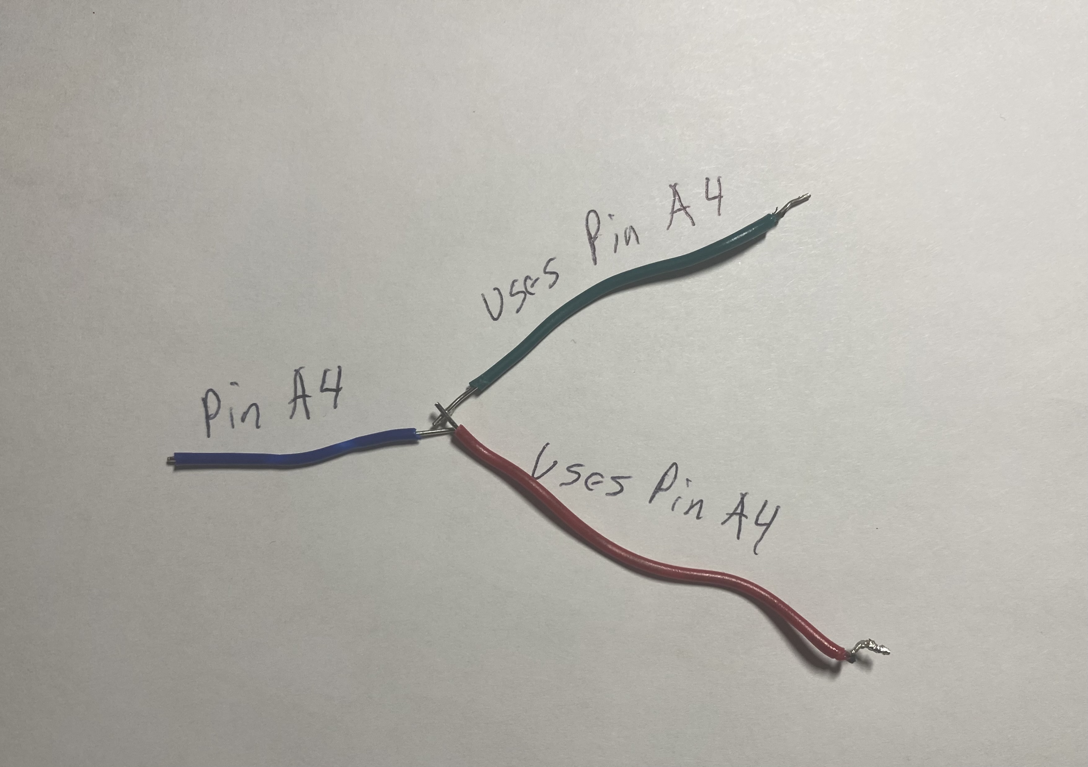
นี่คือตำแหน่งที่จะเชื่อมต่อสายไฟ การเดินสายสำหรับตัวต้านทานอาจจะซับซ้อนเล็กน้อย ดังนั้นผมได้จัดเตรียมรูปภาพด้านล่างเพื่อแสดงวิธีการเดินสาย หากคุณกำลังประกอบจรวดสำหรับพอร์ตบน Nano Every ที่มีสายไฟหลายเส้นนำไปรวมกัน ผมแนะนำให้บัดกรีสายนำ (leader wire) ออกมาเส้นหนึ่ง จากนั้นจึงค่อยเชื่อมต่อสายไฟหลายเส้นเข้ากับปลายอีกด้านหนึ่งของสายนำนั้น แล้วบัดกรีและพันเทปจุดเชื่อมต่อเหล่านั้นให้แน่น ผมมีรูปภาพประกอบด้านล่างเพื่ออธิบายสิ่งที่ผมหมายถึง
เซ็นเซอร์ --> Nano Every
1. MPL3115A2
- Vin --> 5v
- GND --> GND
- SCL --> A5
- SDA --> A4
โมดูล MPL3115A2 เป็นเซ็นเซอร์วัดความดันบรรยากาศและระดับความสูงที่มีความแม่นยำสูงจาก Adafruit นอกจากนี้ยังสามารถวัดอุณหภูมิได้อีกด้วย มันสื่อสารผ่านโปรโตคอล I2C (Inter-Integrated Circuit) ซึ่งใช้เพียงสองสายสัญญาณคือ SDA (Serial Data) และ SCL (Serial Clock) ทำให้ประหยัดขา GPIO ของไมโครคอนโทรลเลอร์ โดยทั่วไปขา A4 และ A5 ของ Arduino Nano Every ถูกกำหนดให้เป็นขา SDA และ SCL ตามลำดับสำหรับการสื่อสาร I2C
2. SHT31
- Vin --> 5v
- GND --> GND
- SCL --> A5
- SDA --> A4
โมดูล SHT31 เป็นเซ็นเซอร์วัดอุณหภูมิและความชื้นสัมพัทธ์ที่มีความแม่นยำสูงอีกตัวหนึ่งจาก Adafruit เช่นเดียวกับ MPL3115A2 มันใช้การสื่อสารแบบ I2C ทำให้สามารถใช้ขา SDA (A4) และ SCL (A5) ร่วมกับเซ็นเซอร์ MPL3115A2 ได้ นี่คือข้อดีของการใช้ I2C ที่อนุญาตให้อุปกรณ์หลายตัวสามารถเชื่อมต่อบนบัสเดียวกันได้ ตราบใดที่มีที่อยู่ I2C ที่แตกต่างกัน
3. Ultimate GPS
- Vin --> 5v
- GND --> GND
- RX --> D7
- TX --> D8
โมดูล Ultimate GPS จาก Adafruit เป็นอุปกรณ์รับสัญญาณ Global Positioning System เพื่อระบุตำแหน่งละติจูด ลองจิจูด ระดับความสูง และเวลา GPS สื่อสารผ่านโปรโตคอล UART (Universal Asynchronous Receiver/Transmitter) โดยใช้ขา RX (รับข้อมูล) และ TX (ส่งข้อมูล) ในกรณีนี้ เราใช้ SoftwareSerial เพื่อสร้างพอร์ตอนุกรมเสมือนบนขา D7 (รับข้อมูลจาก GPS) และ D8 (ส่งข้อมูลไปยัง GPS) เนื่องจาก Arduino Nano Every มี Hardware Serial Port เพียงชุดเดียวซึ่งใช้สำหรับการดีบักผ่าน USB SoftwareSerial ช่วยให้เราสามารถมีพอร์ตอนุกรมเพิ่มเติมได้แม้จะมีข้อจำกัดด้านประสิทธิภาพบางประการ
4. MicroSD card Breakout
- 5v --> 5v
- GND --> GND
- CLK --> D13
- DO --> D12
- DI --> D11
- CS --> (ChipSelect) D10
โมดูล MicroSD card Breakout ใช้สำหรับบันทึกข้อมูลที่รวบรวมได้จากเซ็นเซอร์ลงในการ์ด MicroSD การสื่อสารกับการ์ด SD จะใช้โปรโตคอล SPI (Serial Peripheral Interface) ซึ่งเป็นโปรโตคอลการสื่อสารแบบซิงโครนัสที่เร็วและมีประสิทธิภาพสูง โดยใช้สี่ขาหลัก: * `CLK` (Serial Clock) --> D13 * `DO` (Data Out / Master In, Slave Out - MISO) --> D12 * `DI` (Data In / Master Out, Slave In - MOSI) --> D11 * `CS` (Chip Select) --> D10 (ขา Chip Select นี้ใช้สำหรับเลือกอุปกรณ์ SPI หลายตัวบนบัสเดียวกัน หากมีอุปกรณ์ SPI มากกว่าหนึ่งตัว) * การบันทึกข้อมูลลงในการ์ด SD เป็นสิ่งสำคัญสำหรับการเก็บรักษาข้อมูลที่รวบรวมได้แม้จะขาดการเชื่อมต่อ LoRa
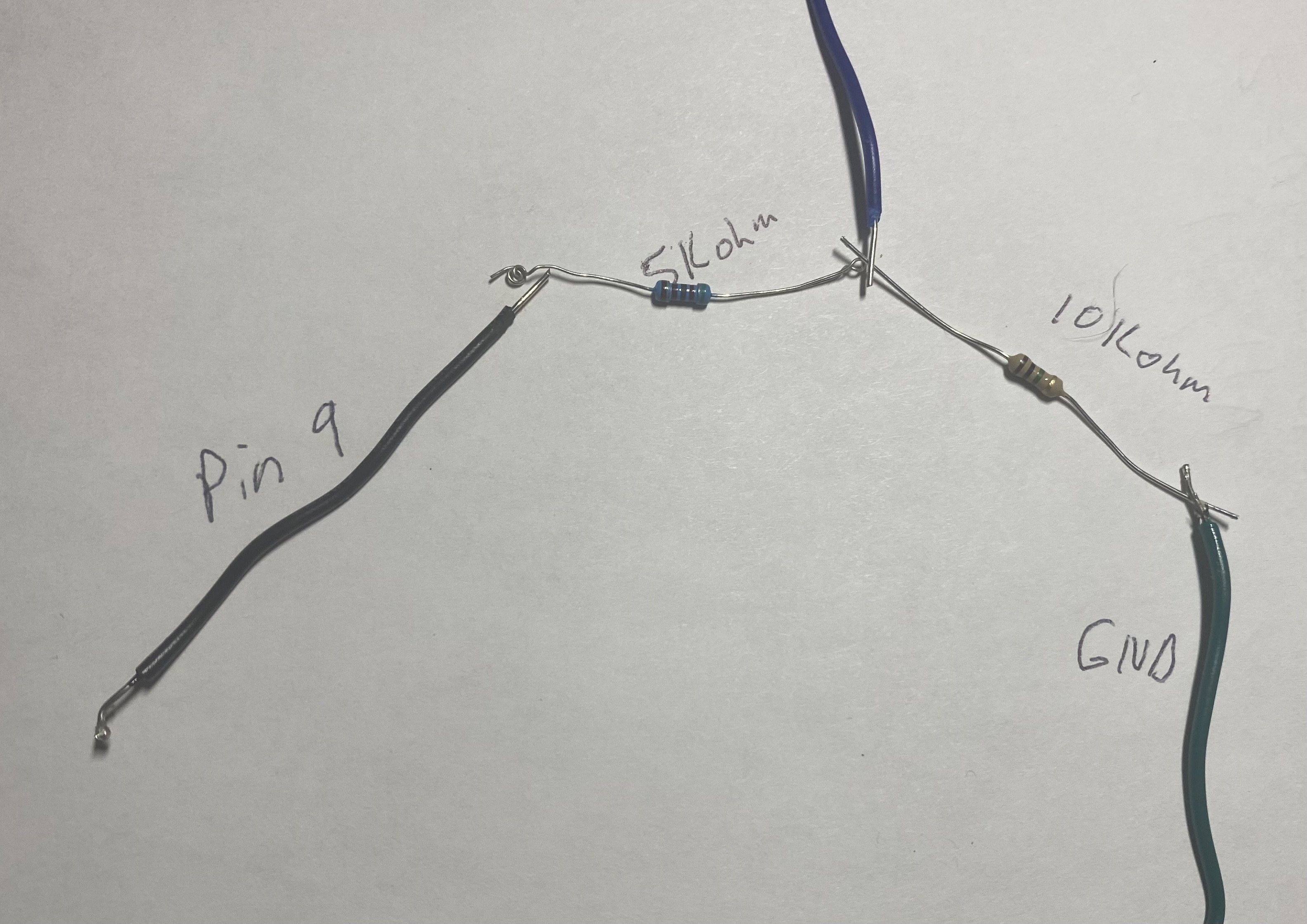
5. LoRa Module
- VDD --> 3.3v
- GND --> GND
- RX --> D9
- 10k Ohm Resisitor D9 --> RX
- 5k Ohm Resistor RX --> GND
โมดูล LoRa (Reyax RYLR890) ใช้สำหรับการส่งข้อมูลแบบไร้สายในระยะไกล โมดูลนี้ทำงานที่แรงดันไฟฟ้า 3.3V ดังนั้นจึงต้องเชื่อมต่อขา VDD เข้ากับ 3.3V ของ Arduino Nano Every และ GND เข้ากับ GND การสื่อสารกับโมดูล LoRa ก็ใช้ SoftwareSerial เช่นกัน โดยขา TX ของ Arduino (D9) จะส่งข้อมูลไปยังขา RX ของโมดูล LoRa อย่างไรก็ตาม เนื่องจาก Arduino Nano Every ทำงานที่ 5V แต่โมดูล LoRa รับสัญญาณได้สูงสุด 3.3V จึงจำเป็นต้องมีวงจรแบ่งแรงดัน (Voltage Divider) สำหรับขา RX ของโมดูล LoRa เพื่อป้องกันความเสียหาย การใช้ตัวต้านทาน 10k โอห์ม และ 5k โอห์ม เป็นการสร้างวงจรแบ่งแรงดันเพื่อลดสัญญาณ 5V จาก Arduino ให้เหลือประมาณ 3.3V ก่อนเข้าสู่ขา RX ของโมดูล LoRa (โดยที่ 10k ต่อกับ D9 และ 5k ต่อจาก RX ของโมดูลไป GND)
6. LED Lights
- 1. D2 and GND for Transmission
- 2. D3 and GND for GPS
ไฟ LED เหล่านี้ใช้เป็นตัวบ่งชี้สถานะง่ายๆ: LED ที่ขา D2 จะกะพริบเมื่อมีการส่งข้อมูลผ่าน LoRa และ LED ที่ขา D3 จะกะพริบเมื่อโมดูล GPS ได้รับสัญญาณดาวเทียม (GPS fix) และข้อมูลพร้อมใช้งาน ซึ่งเป็นสิ่งที่มีประโยชน์สำหรับการตรวจสอบสถานะการทำงานของอุปกรณ์อย่างรวดเร็ว
นี่คือวิธีการเดินสายตัวต้านทาน สาย Ground จะถูกแบ่งครึ่งและควรมีสายอีกเส้นเชื่อมต่ออยู่ซึ่งนำไปสู่ขา ground โดยจะผ่านสาย ground ไป
นี่คือสิ่งที่ผมหมายถึงกับการเพิ่มสายนำ (leader wire) มันจะถูกเดินสายแบบขนาน
*ผมได้เดินสายในลักษณะที่โมดูล LoRa และเสาอากาศ GPS ถูกวางไว้ที่ปลายสุดของส่วนหัวจรวดตามภาพ สายไฟจากพอร์ต 3.3v บน Nano Every ได้ถูกต่อขยายเพื่อให้มีความยาวที่พอดี

3. โค้ด
เมื่อคุณได้ประกอบและเดินสายส่วนประกอบของจรวดเรียบร้อยแล้ว ก็ถึงเวลาทดสอบด้วยโค้ด
อันดับแรก คุณต้องดาวน์โหลดไลบรารี ซึ่งรวมถึง:
1. TinyGPSPlus 2. SD 3. Adafruit_MPL3115A2 4. Adafruit_SHT31.h 5. SoftwareSerial
ไปที่ Tools/Manage Libraries ใน Arduino IDE และพิมพ์ชื่อแต่ละไลบรารีเพื่อค้นหาและติดตั้ง เมื่อเสร็จแล้ว คุณก็พร้อมที่จะคัดลอก/วางโค้ดและอัปโหลดไปยัง Nano Every โดยใช้ปุ่มลูกศรที่มุมซ้ายบนของ IDE
มาทำความเข้าใจโค้ดกัน:
- ไฟล์เฮดเดอร์ด้านล่างจะนำเข้าฟังก์ชันและเมธอดจากไลบรารีที่คุณติดตั้ง ซึ่งทำหน้าที่เชื่อมต่อและสื่อสารกับเซ็นเซอร์ต่างๆ
// Inclusion of necessary libraries for sensor communication, SD card, GPS, and LoRa.
// These libraries abstract the complex underlying communication protocols (I2C, SPI, UART).
#include "Adafruit_SHT31.h" // Library for the SHT31 temperature and humidity sensor (I2C)
#include <Adafruit_MPL3115A2.h> // Library for the MPL3115A2 barometric pressure, altitude, and temperature sensor (I2C)
#include <SPI.h> // Standard library for SPI communication, used by the SD card module
#include <SD.h> // Library for interacting with SD cards, built on SPI
#include <Arduino.h> // Core Arduino functions (e.g., pinMode, digitalWrite)
#include <Wire.h> // Library for I2C (Two-Wire Interface) communication, used by SHT31 and MPL3115A2
#include <SoftwareSerial.h> // Library to enable serial communication on any digital pins, used for GPS and LoRa
#include "TinyGPS++.h" // Library for parsing NMEA sentences from GPS modules
- บรรทัดถัดไปจะกำหนดพอร์ตบน Nano Every ที่จะใช้สำหรับ LED สร้างพอร์ต TX และ RX ด้วย Software Serial และสร้างตัวแปร global ที่จะใช้ในส่วนต่างๆ ของโค้ด
// Pin definitions for LEDs and SoftwareSerial ports. Global variables for sensor objects and data.
#define pin 2 // Define digital pin 2 for the LED indicating LoRa data transmission.
#define gpsPin 3 // Define digital pin 3 for the LED indicating GPS fix.

// SoftwareSerial objects for communication with GPS and Reyax LoRa modules.
// Syntax: SoftwareSerial(RX_PIN, TX_PIN).
// For GPS: Arduino RX (D8) connects to GPS TX, Arduino TX (D7) connects to GPS RX.
// For Reyax: Arduino RX (D8) connects to Reyax TX, Arduino TX (D9) connects to Reyax RX.
// Note: The original code has GPS(8, 7) and Reyax(8, 9). This implies pin D8 is shared as RX for both, which is problematic.
// A proper setup would use two distinct pairs of SoftwareSerial pins or hardware serial if available.
// For this project, assuming D8 is used as RX for both if they are not active simultaneously, or there's an error in the snippet.
// Let's assume for a single RX pin, it's connected to one of them and the other is either unused or an error.
// Given the wiring diagram, Arduino D7 (SoftwareSerial TX) connects to GPS RX. Arduino D8 (SoftwareSerial RX) connects to GPS TX.
// For Reyax, Arduino D9 (SoftwareSerial TX) connects to Reyax RX (via voltage divider). Arduino D8 (SoftwareSerial RX) connects to Reyax TX.
// This means D8 is the common RX for both. This can work if only one device transmits at a time, or if the Reyax's TX is connected to a different pin.
// Let's adhere to the snippet: D8 is RX for both defined SoftwareSerial instances. This is a potential issue in a real-world scenario if both devices transmit simultaneously.
// In the context of the provided snippet, it means the Arduino's pin 8 will receive data for both.
// Pin 7 will transmit for GPS. Pin 9 will transmit for Reyax.
SoftwareSerial GPS(8, 7); // RX (Arduino D8 listens), TX (Arduino D7 talks) for GPS module.
SoftwareSerial Reyax(8, 9); // RX (Arduino D8 listens), TX (Arduino D9 talks) for Reyax LoRa module.
TinyGPSPlus tinygps; // Creates an instance of the TinyGPSPlus library to parse GPS data.
Adafruit_SHT31 sht31 = Adafruit_SHT31(); // Creates an instance of the SHT31 sensor object. Default I2C address is 0x44.
Adafruit_MPL3115A2 baro; // Creates an instance of the MPL3115A2 barometric sensor object.
// Defines the Chip Select pin for the SD card module, essential for SPI communication.
const int chipSelect = 10;
// Current sea level pressure in hPa (hectopascals).
// This value is crucial for accurate altitude calculations by the MPL3115A2 sensor.
// It should be updated to the local sea level pressure for the best accuracy before launch.
const double currentPressure = 1013.26;
int id = 0; // A counter variable to assign a unique ID to each data observation.
- ฟังก์ชัน
setup()จะตรวจสอบการเดินสายและให้แน่ใจว่าทุกอย่างทำงานได้อย่างถูกต้อง ส่วนของ SD card reader อาจพบปัญหาได้บ่อยที่สุด ดังนั้นโปรดระมัดระวังในการเดินสาย นี่คือโค้ดsetupสำหรับเครื่องส่งสัญญาณ:
// The setup() function runs once when the sketch starts or after a reset.
void setup() {
  // Initialize digital pins for LEDs as outputs.
  pinMode(pin, OUTPUT); // LED for LoRa transmission status.
  pinMode(gpsPin, OUTPUT); // LED for GPS fix status.
  // Start hardware serial communication for debugging purposes via USB.
  Serial.begin(9600);
  // Start SoftwareSerial communication for the Reyax LoRa module at 38400 baud,
  // matching the AT+IPR setting done previously.
  Reyax.begin(38400);
  // Start SoftwareSerial communication for the GPS module at its default baud rate, usually 9600.
  GPS.begin(9600);
  // Sensor Initialization and Wiring Checks:
  // Test SHT31 Sensor:
  Serial.println("SHT31 test");
  // Attempt to initialize the SHT31 sensor. It uses I2C address 0x44 by default.
  // If initialization fails, it prints an error and halts execution.
  if (! sht31.begin(0x44)) {
    Serial.println("Couldn't find SHT31");
    while (1) delay(1); // Infinite loop to indicate a fatal error.
  }
  // Test MPL3115A2 Sensor:
  Serial.println("Adafruit_MPL3115A2 test!");
  // Attempt to initialize the MPL3115A2 sensor. It also uses I2C.
  // If initialization fails, it prints an error and halts execution.
  if (!baro.begin()) {
    Serial.println("Could not find sensor. Check wiring.");
    while (1); // Infinite loop for fatal error.
  }
  // Set the sea level pressure for accurate altitude calculation.
  // The MPL3115A2 measures absolute pressure, but altitude calculation requires a reference sea level pressure.
  baro.setSeaPressure(currentPressure);
  // SD Card Initialization:
  Serial.print("Initializing SD card...");
  // Attempt to initialize the SD card module using the specified chipSelect pin.
  // If initialization fails, it prints an error and halts execution.
  if (!SD.begin(chipSelect)) {
    Serial.println("Card failed, or not present");
    while (1); // Infinite loop for fatal error.
  }
  Serial.println("card initialized.");
  Serial.println("Setup complete");
  // The loop() function will start running once this message is printed to Serial Monitor.
}
- ฟังก์ชัน
loop()จะทำงานอย่างต่อเนื่องเป็นรอบวนซ้ำจนกว่าคุณจะออกจากฟังก์ชันนี้หรือปิดเครื่องอุปกรณ์
- ส่วนของโค้ดนี้จะตรวจสอบว่ามีข้อมูล GPS พร้อมใช้งานหรือไม่ จากนั้นจะแยกวิเคราะห์ประโยค NMEA ของ GPS เพื่อรับข้อมูลละติจูด ลองจิจูด ระดับความสูง และความเร็ว
// The loop() function runs repeatedly after setup().
void loop() {
// GPS Data Acquisition and Parsing:
// Continuously read incoming data from the GPS module.
// The GPS.available() checks if there are bytes to read from the SoftwareSerial port connected to GPS.
 while (GPS.available() > 0) {
   // tinygps.encode(GPS.read()) feeds each byte from the GPS module into the TinyGPS++ parser.
   // It returns true if a complete, valid NMEA sentence has been processed and new data is available.
   if (tinygps.encode(GPS.read())) {
     digitalWrite(gpsPin, HIGH);   // Turn on the GPS status LED to indicate a successful GPS fix/data update.
     delay(100);                   // Keep the LED on briefly.
     digitalWrite(gpsPin, LOW);    // Turn off the LED. This creates a quick blink.
   }
 }
- โค้ดนี้จะสร้างสตริงว่าง (empty strings) และจากนั้นจะนำข้อมูลจากเซ็นเซอร์มาใส่ในสตริงเหล่านั้นเพื่อใช้ในการส่งและบันทึกข้อมูลลงในการ์ด SD
// Data Collection from Sensors and GPS, converting to String format.
 // Initialize empty String objects to hold sensor and GPS data.
 String pressureString = "";
 String altitudeString = "";
 String temperatureString = "";
 String humidityString = "";
 String latitudeString = "";
 String longitudeString = "";
 String speedString = "";
 String idString = "";
 String hourString = "";
 String minuteString = "";
 String secondString = "";
 String timeString = "";
 String dataString = "";
 // Concatenate (append) sensor readings into their respective String variables.
 // baro.getPressure() returns pressure in Pascals, needs conversion if hPa is desired. (Library returns hPa usually).
 pressureString.concat(baro.getPressure());
 // tinygps.altitude.meters() returns altitude in meters.
 altitudeString.concat(tinygps.altitude.meters());
 // baro.getTemperature() returns temperature in Celsius.
 temperatureString.concat(baro.getTemperature());
 // sht31.readHumidity() returns humidity in percentage.
 humidityString.concat(sht31.readHumidity());
 // tinygps.location.lng() and tinygps.location.lat() return longitude and latitude as double.
 // String(value, decimal_places) converts double to string with specified precision.
 latitudeString.concat(String(tinygps.location.lat(),6)); // Latitude with 6 decimal places.
 longitudeString.concat(String(tinygps.location.lng(),6)); // Longitude with 6 decimal places.
 // tinygps.speed.kmph() returns speed in kilometers per hour.
 speedString.concat(tinygps.speed.kmph());
 // Extract time components (hour, minute, second) from GPS data.
 hourString.concat(tinygps.time.hour());
 minuteString.concat(tinygps.time.minute());
 secondString.concat(tinygps.time.second());
- โค้ดนี้สร้าง
timeStringและDataStringให้อยู่ในรูปแบบที่เราต้องการTimeStringอยู่ในรูปแบบ XX:XX:XX โดยจับเวลาแบบ UTC และdataStringจะถูกบันทึกเป็นค่าที่คั่นด้วยเครื่องหมายจุลภาค (CSV) เพื่อให้ง่ายต่อการบันทึก นอกจากนี้ยังมีตัวแปรตัวนับIDเพื่อช่วยระบุว่ามีการเก็บข้อมูลการสังเกตใด
// Formatting Time and Data Strings for transmission and logging.
 // Construct the time string in "HH:MM:SS" format using UTC time from GPS.
 timeString += hourString;
 timeString += ":";
 timeString += minuteString;
 timeString += ":";
 timeString += secondString;
 // Increment the data ID counter for each observation.
 idString = String(id++);
 // Construct the main data string in Comma Separated Values (CSV) format.
 // This format is highly readable and easily importable into spreadsheet software for analysis.
 dataString += idString;
 dataString += ",";
 dataString += temperatureString; // Temperature data.
 dataString += ",";
 dataString += humidityString;    // Humidity data.
 dataString += ",";
 dataString += pressureString;    // Pressure data.
 dataString += ",";
 dataString += altitudeString;    // Altitude data.
 dataString += ",";
 dataString += latitudeString;    // Latitude data.
 dataString += ",";
 dataString += longitudeString;   // Longitude data.
 dataString += ",";
 dataString += speedString;       // Speed data.
 dataString += ",";
 dataString += timeString;        // Timestamp.
- โค้ดนี้เป็นส่วนที่ใช้ในการส่งข้อมูล มันใช้คำสั่ง AT "AT+SEND=" เพื่อส่งข้อมูลไปยังที่อยู่เฉพาะ นี่คือจุดที่คุณต้องเขียนที่อยู่เครื่องรับที่คุณเลือกไว้ในขั้นตอนที่ 1 มันจะสร้างสตริงดังนี้:
AT+SEND=0, จำนวนตัวอักษรใน dataString, dataStringหลังจากนี้ ไฟ LED จะกะพริบเพื่อส่งสัญญาณว่าข้อมูลได้ถูกส่งไปแล้ว
// LoRa Data Transmission:
// This section prepares and sends the collected data string via the Reyax LoRa module.
 // The AT command for sending data is "AT+SEND=,,".
 // "0" is assumed to be the receiver address as specified in the original instruction, though it's recommended to change it.
 String first = "AT+SEND=0,";
 // Append the length of the data string. The LoRa module needs to know the payload size.
 first += String(dataString.length());
 first += ",";
 // Append the actual data string.
 first += String(dataString);
 // Send the complete AT command string to the Reyax LoRa module via SoftwareSerial.
 Reyax.println(first);
 // Blink the transmission status LED to indicate data has been sent.
 digitalWrite(pin, HIGH);
 delay(100);
 digitalWrite(pin, LOW);
- โค้ดนี้จะบันทึกข้อมูล
dataStringลงในการ์ด SD เนื่องจากถูกนำไปใช้เป็นข้อมูล CSV ชื่อไฟล์จึงต้องลงท้ายด้วย .csv นอกจากนี้ สามารถเปิดไฟล์ได้ครั้งละ 1 ไฟล์เท่านั้น และคุณต้องปิดไฟล์หลังจากใช้งาน หากคุณได้รับข้อผิดพลาด แสดงว่าคุณไม่ได้บันทึกข้อมูล
// SD Card Data Logging:
// This section writes the collected data string to a file on the MicroSD card.
 // Open the file "datalog.csv" in write mode (FILE_WRITE).
 // If the file does not exist, it will be created. If it exists, new data will be appended to the end.
 File dataFile = SD.open("datalog.csv", FILE_WRITE);
 // Check if the file was opened successfully.
 if (dataFile) {
   dataFile.println(dataString); // Write the dataString followed by a newline character to the file.
   dataFile.close(); // Crucial: Close the file to ensure all data is written and saved properly, preventing corruption.
 }
 else {
   // If the file could not be opened, print an error message to the Serial Monitor.
   Serial.println("error opening datalog.txt"); // Note: The error message refers to "datalog.txt" but the file opened is "datalog.csv". This might be a typo.
 }
- เครื่องรับมีโค้ดที่คล้ายกัน แต่ต้องมีการแยกวิเคราะห์ข้อความ
+RCVเพื่อดึงข้อมูลที่เราต้องการ ส่วนแรกจะตรวจสอบว่ามีข้อมูลส่งมาหรือไม่ หากได้รับ มันจะอ่านข้อมูลและบันทึกไว้ในสตริงที่ชื่อว่าreceivedถัดไปมันจะส่งสัญญาณว่าได้รับข้อมูลแล้วโดยการกระพริบ LED หลังจากนั้นมันจะแยกวิเคราะห์ข้อความ+RCVโดยใช้substringและindexOfเพื่อหาความยาวและข้อความจริงที่ส่งมา โดยข้อมูลที่ถูกแยกออกมาจะถูกบันทึกในตัวแปรmessageจากนั้นตัวแปรmessageนี้จะถูกนำไปใช้ในโค้ดที่คล้ายกันกับที่กล่าวมาข้างต้นเพื่อบันทึกลงในการ์ด SD
// Receiver Code Logic (Conceptual based on description):
// This snippet demonstrates the logic for a LoRa receiver module to process incoming data.
 // Check if there's any data available to read from the Reyax LoRa module's SoftwareSerial port.
 if (Reyax.available()) {
   // Read the incoming string from the LoRa module.
   // The received data will typically be in the format: "+RCV=,,"
   String received = Reyax.readString();
   // Blink an LED to indicate that data has been received.
   digitalWrite(pin, HIGH);
   delay(100);
   digitalWrite(pin, LOW);
   // Check if the received string contains the "+RCV" header, indicating a valid LoRa reception.
   // indexOf() returns the position of the substring, or -1 if not found.
   if (received.indexOf("+RCV") >= 0) {
     // Variables to store the indices of commas, used for parsing the string.
     int parser, parser_1, parser_2, parser_3;
 <span class="hljs-comment">// Find the first comma after "+RCV". This marks the end of the sender address.</span>
 parser = received.indexOf(<span class="hljs-string">","</span>);
 <span class="hljs-comment">// Find the second comma, marking the end of the data length.</span>
 parser_1 = received.indexOf(<span class="hljs-string">","</span>, parser + <span class="hljs-number">1</span>);
 <span class="hljs-comment">// Find the third comma (not strictly needed for this parsing but might be for other data types).</span>
 parser_2 = received.indexOf(<span class="hljs-string">","</span>, parser_1 + <span class="hljs-number">1</span>);

 <span class="hljs-comment">// Extract the data length string and convert it to an integer.</span>
 <span class="hljs-comment">// substring(start_index, end_index) extracts a portion of the string.</span>
 <span class="hljs-comment">// +1 is used to skip the comma itself.</span>
 <span class="hljs-type">int</span> lenMessage = received.substring(parser + <span class="hljs-number">1</span>, parser_1).toInt();

 <span class="hljs-comment">// Extract the actual data message using the parsed length.</span>
 String message = received.substring(parser_1 + <span class="hljs-number">1</span>, parser_1 + lenMessage + <span class="hljs-number">1</span>);

 <span class="hljs-comment">// At this point, the 'message' variable holds the clean CSV data string.</span>
 <span class="hljs-comment">// This 'message' can then be parsed further (e.g., using String.split() or custom parsing)</span>
 <span class="hljs-comment">// and saved to an SD card, displayed on an LCD, or sent to another system.</span>

 <span class="hljs-comment">// Example of what might follow (not in original snippet, but implied by text):</span>
 <span class="hljs-comment">// File rxDataFile = SD.open("rxlog.csv", FILE_WRITE);</span>
 <span class="hljs-comment">// if (rxDataFile) {</span>
 <span class="hljs-comment">//   rxDataFile.println(message);</span>
 <span class="hljs-comment">//   rxDataFile.close();</span>
 <span class="hljs-comment">// } else {</span>
 <span class="hljs-comment">//   Serial.println("Error opening receiver datalog.");</span>
 <span class="hljs-comment">// }</span>

   }
 }
*ห้ามคัดลอกและวางจากบล็อกโค้ดด้านบน ให้ใช้โค้ดที่อยู่ในส่วนโค้ดหลัก
เมื่อคุณเขียนโค้ดสำหรับอุปกรณ์แล้ว ให้ทดสอบดู ข้อมูล GPS จะใช้เวลาพอสมควรกว่าที่ระบบจะรับสัญญาณ (fix) จากดาวเทียมได้ ส่วนเซ็นเซอร์อื่นๆ ควรจะส่งข้อมูลกลับมาทันที
4. การประกอบจรวด
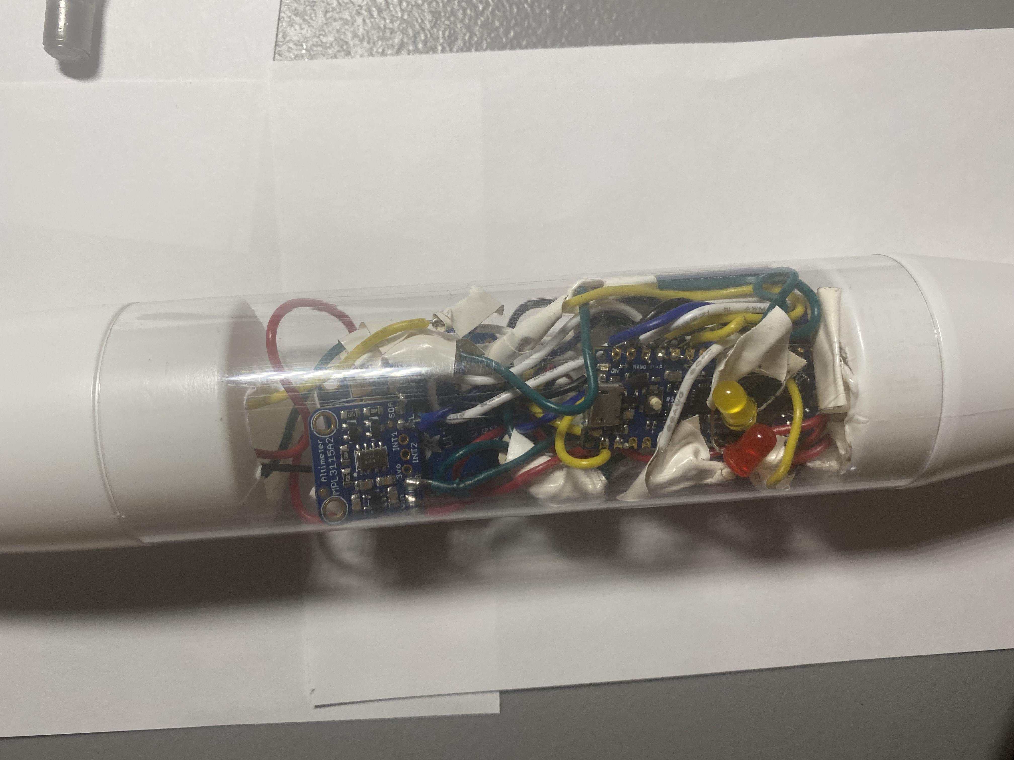
เมื่อคุณได้เดินสายและเขียนโค้ดสำหรับอุปกรณ์เซ็นเซอร์ของคุณเรียบร้อยแล้ว ก็ถึงเวลาที่จะนำไปติดตั้งในจรวด ผมใช้ชุด Estes Loadstar II เนื่องจากมีแคปซูลที่สามารถใส่อุปกรณ์นี้ได้พอดี ผมได้ดัดแปลงส่วนหัวจรวดและส่วนท้ายเพื่อติดตั้งโมดูล Reyax ไว้ด้านบนและแบตเตอรี่ 9V ไว้ในส่วนล่าง คุณสามารถใช้มีดคัตเตอร์เพื่อตัดส่วนเหล่านั้นออก ผมประกอบมันเข้าด้วยกันดังนี้:
- โมดูล Reyax และเสาอากาศ GPS ในส่วนหัวจรวด การวางเสาอากาศ GPS และ LoRa ไว้ที่ส่วนหัวจะช่วยให้สามารถรับส่งสัญญาณได้ดีที่สุด เนื่องจากเป็นส่วนที่ไม่มีสิ่งกีดขวาง
- ส่วนใหญ่ของเซ็นเซอร์ในท่อใส ซึ่งเป็นส่วนที่ป้องกันเซ็นเซอร์จากสภาพแวดล้อมภายนอก
- แบตเตอรี่ 9V ในส่วนท้าย ซึ่งให้พลังงานที่เพียงพอสำหรับอุปกรณ์อิเล็กทรอนิกส์ทั้งหมด
ผมได้ใช้กาวเชื่อมส่วนหัวจรวดเข้ากับท่อพลาสติกใส และยังไม่ได้เชื่อมส่วนท้ายเข้าด้วยกัน เพื่อให้สามารถต่อแบตเตอรี่ 9V เข้ากับสายไฟได้ เมื่อผมพร้อมที่จะใช้งาน ผมจะใช้กาวเชื่อมส่วนต่างๆ เข้าด้วยกันและประกอบให้สมบูรณ์ นี่คือรูปถ่ายส่วนเซ็นเซอร์ของจรวดของผม:
5. ข้อแนะนำ
- เจาะรูเล็กๆ ในส่วนพลาสติกใส เพื่อให้อากาศถ่ายเทสำหรับเซ็นเซอร์วัดอุณหภูมิและความชื้น การระบายอากาศที่ดีจะช่วยให้เซ็นเซอร์เหล่านี้สามารถวัดค่าสภาพแวดล้อมภายนอกได้อย่างแม่นยำยิ่งขึ้น
- จรวดนี้พร้อมกับร่มชูชีพจะทำหน้าที่เสมือนก้อนอากาศ (air parcel) ที่เคลื่อนที่ผ่านชั้นบรรยากาศ ซึ่งหมายความว่ามันจะเก็บข้อมูลจากสภาพแวดล้อมต่างๆ ที่พายุทอร์นาโดเคลื่อนที่ผ่าน ซึ่งเป็นข้อมูลที่มีค่าสำหรับการวิจัย
- ใส่ข้อมูลที่อนุญาตให้ผู้ที่พบจรวดติดต่อคุณได้ หากจรวดถูกค้นพบ ข้อมูลที่บันทึกไว้จะสมบูรณ์ที่สุด การติดตามด้วย GPS อาจจำกัดระยะทาง หากจรวดเดินทางเกิน 5 ไมล์ คุณอาจไม่สามารถระบุตำแหน่งได้จากพิกัด GPS ที่ส่งมาอย่างต่อเนื่องเท่านั้น การมีช่องทางการติดต่อจะเพิ่มโอกาสในการกู้คืนอุปกรณ์และข้อมูล
- พยายามค้นหาจรวดทันทีหลังจากการกางร่มชูชีพ (deployment) ติดตามพายุอย่างใกล้ชิดเพื่อให้เครื่องรับสามารถรับข้อมูลตำแหน่งได้เมื่อจรวดถึงพื้นดิน การตอบสนองที่รวดเร็วจะช่วยเพิ่มโอกาสในการกู้คืนและป้องกันความเสียหายต่ออุปกรณ์และข้อมูล
ขอให้โชคดี และอย่าลังเลที่จะส่งข้อความหาผมทาง Twitter หากคุณได้สร้างมันขึ้นมา มีข้อมูล หรือมีคำถามใดๆ ได้ที่ @tknep3