1. บทนำ
เจ้า [Arduino](https://s.shopee.co.th/7fUgFAWSki) GSM shield เนี่ย มันทำให้เราควบคุมบอร์ด Arduino ได้หลายวิธีเลยนะฮะ เนื้อหานี้จะช่วยให้น้องๆ เข้าใจว่าเราจะใช้ SMS ง่ายๆ มาควบคุมเอาต์พุตของบอร์ดยังไง โปรเจกต์นี้เดิมทีทำขึ้นสำหรับเสาไฟแบบอินเทอร์แอคทีฟ ที่เอาไปโชว์ในงานประชุมประจำปีของ Innovation Center of Iceland ในเดือนกุมภาพันธ์ 2014 นอกเหนือจากอุปกรณ์ในลิสต์แล้ว ก็ใช้ WS2801 digital RGB LED pixel string กับแหล่งจ่ายไฟ 5V ด้วยนะ ตัว LED string WS2801 เนี่ย มีชิปคอนโทรลเลอร์ต่อกับแต่ละ Pixel เลย ทำให้เราควบคุมความสว่างและสีของแต่ละ Pixel แยกกันได้เลย งานนี้หล่อเท่เลย
โค้ด Sketch นี้ปรับแต่งง่ายมาก จะเอาไปควบคุม [Relay](https://s.shopee.co.th/3fyXTmWPbL), มอเตอร์ หรือเอาต์พุตอื่นๆ ตามใจน้องก็ได้
หน้าจอ [LCD](https://s.shopee.co.th/6AfsSPcAnb) ไม่จำเป็นต้องใช้ก็ได้นะ แต่ถ้าน้องเซ็ตระบบนี้ไว้ในที่ที่ใช้ Serial Monitor ไม่ได้ การเห็นสถานะการเชื่อมต่อ GSM และข้อความที่ได้รับบนหน้าจอก็ช่วยได้เยอะเลยล่ะ
2. วงจร (The Circuit)
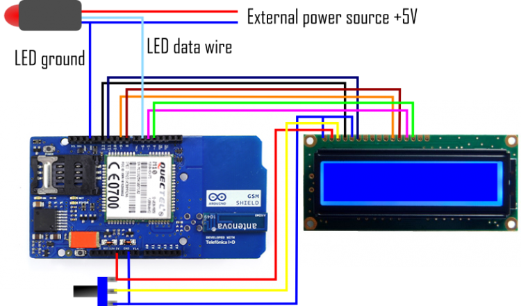
ต่อ LED pixel string เข้ากับ GSM shield กันเลย โดยสาย Data ต่อกับ Pin 6 และสาย Ground ก็ต่อกับ... Ground นั่นแหละฮะ 555 สำหรับการต่อหน้าจอ [LCD](https://s.shopee.co.th/6AfsSPcAnb) เข้ากับ [Arduino](https://s.shopee.co.th/7fUgFAWSki) ให้ต่อขาต่อไปนี้:
- [LCD](https://s.shopee.co.th/6AfsSPcAnb) RS pin ไปที่ digital pin 12
- [LCD](https://s.shopee.co.th/6AfsSPcAnb) Enable pin ไปที่ digital pin 11
- [LCD](https://s.shopee.co.th/6AfsSPcAnb) D4 pin ไปที่ digital pin 5
- [LCD](https://s.shopee.co.th/6AfsSPcAnb) D5 pin ไปที่ digital pin 4
- [LCD](https://s.shopee.co.th/6AfsSPcAnb) D6 pin ไปที่ digital pin 3
- [LCD](https://s.shopee.co.th/6AfsSPcAnb) D7 pin ไปที่ digital pin 2
นอกจากนี้ ต่อ Potentiometer 10K ระหว่าง +5V กับ GND แล้วเอาขา Wiper (Output) ไปต่อกับขา VO (pin3) ของหน้าจอ [LCD](https://s.shopee.co.th/6AfsSPcAnb) ด้วยนะ
ต่อแหล่งจ่ายไฟภายนอกเข้ากับ LED string ถ้าน้องใช้ LED string หลายเส้น ให้ต่อสาย Data และ Ground แบบอนุกรมกัน แต่แนะนำให้ต่อ LED string แต่ละเส้นแบบขนานกับแหล่งจ่ายไฟจะดีที่สุด
จริงๆ แล้ว เราสามารถใช้แบตเตอรี่ 9V ก้อนเดียวจ่ายไฟให้ทั้ง [Arduino](https://s.shopee.co.th/7fUgFAWSki) พร้อม GSM shield และ LED strip หนึ่งเส้นได้เลยนะ งานนี้จัดไปวัยรุ่น!
3. โครงสร้างของ Sketch
Sketch นี้แบ่งออกเป็น 4 ส่วน (ไม่นับบทนำ) ส่วนแรกคือการเรียกใช้ Libraries, กำหนดค่าคงที่ และตัวแปรระดับ Global ส่วนที่สองคือการตั้งค่าการสื่อสาร ส่วนที่สามคือ Loop หลัก และส่วนที่สี่คือการกำหนด Functions ต่างๆ
โค้ดสำหรับหน้าจอ [LCD](https://s.shopee.co.th/6AfsSPcAnb) ส่วนใหญ่จะอยู่ด้วยกันเป็นกลุ่มๆ ทำให้ง่ายต่อการ Comment ออกหรือลบทิ้งถ้าไม่ได้ใช้ แต่มันก็ไม่จำเป็นต้องมีก็ได้นั่นแหละ
4. การกำหนดตัวแปร Global, ค่าคงที่ และการเรียก Libraries
มี Libraries อยู่ 3 ตัวที่ต้องเรียกใช้ใน Sketch นี้ ตัวหนึ่งสำหรับ GSM shield, ตัวหนึ่งสำหรับหน้าจอ [LCD](https://s.shopee.co.th/6AfsSPcAnb) และอีกตัวสำหรับ Pixel strip สองตัวแรกเป็นส่วนหนึ่งของ [Arduino](https://s.shopee.co.th/7fUgFAWSki) IDE อยู่แล้ว แต่ตัวสุดท้ายน้องต้องดาวน์โหลดมาและติดตั้งในระบบเอง
ถ้าน้องคล่องเรื่อง Libraries แล้ว ลองเปิด Libraries เหล่านี้ขึ้นมาแล้วปรับแต่งให้เล็กลงได้นะ เช่น Library GSM นี่ใหญ่ดี แต่ในโปรเจกต์นี้เราใช้แค่ฟังก์ชัน SMS เท่านั้น ดังนั้นเราสามารถตัดส่วน Voice call หรือ Data network ออกไปได้เลย แค่จำไว้ว่าให้เซฟเป็น Library ใหม่ด้วยชื่ออื่นนะ จะได้ยังใช้ Library GSM.h ตัวเต็มๆ ได้ในอนาคต
ต่อมาเป็นการกำหนดค่าคงที่ (Constants) สองสามตัว เริ่มจาก PINNUMBER ที่ใช้ตอน GSM shield เปิดใช้งาน SIM card ตัวที่สองคือการประกาศขาเอาต์พุตสำหรับ LED pixels ส่วนค่าคงที่สุดท้ายคือการประกาศขาเอาต์พุตสำหรับหน้าจอ [LCD](https://s.shopee.co.th/6AfsSPcAnb)
ต่อไปคือการตั้งค่าฟังก์ชันสำหรับ LED pixels โดยการเรียก Class Adafruit_NeoPixel จาก Adafruit NeoPixel library มาใช้ ซึ่งในที่นี้ตั้งชื่อว่า LED
Adafruit_NeoPixel LED = Adafruit_NeoPixel(150, PIN, NEO_GRB + NEO_KHZ400);
Class นี้รับตัวแปร 4 ตัวที่น้องสามารถเปลี่ยนได้ถ้าการตั้งค่าของน้องต่างออกไป เช่น ถ้ามีไฟน้อยกว่าหรือใช้ LED pixels คนละประเภท
ตัวแปรแรกคือจำนวนไฟ LED ในที่นี้คือ 150 ดวง ตัวแปรที่สองคือขาเอาต์พุต ซึ่งในที่นี้กำหนดด้วยค่าคงที่ PIN ที่ประกาศไว้ก่อนหน้าและตั้งค่าเป็น 6
ตัวแปรถัดไปกำหนดวิธีการเดินสายของ Pixels;
- NEO_GRB สำหรับ GRB bitstream (Green, Red, Blue) ส่วนใหญ่ใช้กับ neopixels
- NEO_RGB สำหรับ RGB bitstream (Red, Green, Blue)
สุดท้ายคือการกำหนดความถี่ของ Bitstream
- NEO_KHZ800 สำหรับ bitstream 800 KHz
- NEO_KHZ400 สำหรับ bitstream 400 KHz
สำหรับการทำงานกับ GSM shield เราเรียก Class สองตัวจาก GSM library มาใช้ เริ่มจากเรียก Class GSM function ซึ่งในที่นี้ตั้งชื่อว่า gsmAccess แล้วตามด้วย Class GSM_SMS function ซึ่งตั้งชื่อว่า SMS
ส่วนสุดท้ายของบทที่ 1 คือการประกาศตัวแปร Global ซึ่งสามารถเข้าถึงได้จากที่ไหนก็ได้ใน Sketch
#include <Adafruit_NeoPixel.h> // This includes Pixel library from ADAFRUIT. Awailable here https://github.com/adafruit/Adafruit_NeoPixel
#include <GSM.h> // This includes the GSM library, included in your [Arduino](https://s.shopee.co.th/7fUgFAWSki) IDE
#include <LiquidCrystal.h> // This includes the [LCD](https://s.shopee.co.th/6AfsSPcAnb) library, included in your Arduino IDE
#define PINNUMBER "" // declaration of the constant PINNUMBER used to push the pin number of the SIM card
#define PIN 6 // declaration of the constant PIN, and setting it to output nr. 6
LiquidCrystal lcd(12, 11, 9, 8, 5, 4); // sets the pinnumbers used for the LCD display. Comment out if no LCD
Adafruit_NeoPixel LED = Adafruit_NeoPixel(150, PIN, NEO_GRB + NEO_KHZ400);
/* This sets values to the variables in the NeoPixel class function.
First variable is the number of lights,
then it is the output, previously defined as nr.6
Next variable sets how the pixels are wired
  NEO_GRB is for GRB bitstream (Green, Red, Blue) most neopixels
  NEO_RGB is for RGB bitstream (Red, Green, Blue)
Finally it addresses the frequency of the bitstream
  NEO_KHZ800 for 800 KHz bitstream
  NEO_KHZ400 for 400 KHz bitstream
*/
GSM gsmAccess; // opens up GSM access on the shield.
GSM_SMS sms;
char remoteNumber[20]; // Variable to store the remote number from the modem.
char c; //Variable for reading the sms messages from the SIM card
char m; //Variable for storing the first letter in each messages
int x=0; //Counter for the number of SMS messages processed
char lastm; //Variable to stop SMS replying
String lastMess; //for storing the whole message
int countR, countG, countB, countY, countW, countP, countO; //Counters for keeping information on how often each class is called
5. Setup
ส่วน Setup นี้ส่วนใหญ่ใช้สำหรับตั้งค่า GSM shield นอกจากนี้ยังมีการตั้งค่าการตรวจสอบสองแบบและตั้งค่าสำหรับไฟ LED อีกด้วย วิธีแรกคือ Serial Monitor และวิธีที่สองคือหน้าจอ [LCD](https://s.shopee.co.th/6AfsSPcAnb) การมี Serial Monitor ทำงานไว้ตอนทดสอบการเชื่อมต่อและปรับแต่ง Sketch จะช่วยได้มากเลย ถ้าน้องอยากทดสอบฮาร์ดแวร์หรืออัพเดตซอฟต์แวร์ในภายหลัง การมี Serial Monitor ทำงานไว้ก็ดีเหมือนกัน ส่วนหน้าจอ LCD อย่างที่บอกไป มันไม่จำเป็น แต่ถ้า [Arduino](https://s.shopee.co.th/7fUgFAWSki) กับ GSM shield ของน้องไม่ได้ต่อกับคอมพิวเตอร์ การเห็นสถานะของระบบบนหน้าจอก็เป็นเรื่องดี แม้แต่การเพิ่มปุ่มกดเพื่อดึงข้อมูลเพิ่มเติมจากซอฟต์แวร์มาแสดงบนหน้าจอ เช่น จำนวนข้อความที่ได้รับ ก็ยังทำได้เลย สู้งานนะน้อง!
การตั้งค่า GSM นั้นตรงไปตรงมา เริ่มจากกำหนดตัวแปร Boolean ชื่อ notConnected และตั้งค่าเป็น true ตัวแปรนี้บ่งชี้ว่า GSM shield มีการเชื่อมต่อเครือข่ายหรือไม่ (ถ้าเป็น true คือยังไม่เชื่อมต่อ, ถ้าเป็น false คือเชื่อมต่อแล้ว) ต่อมามี While loop ที่พยายามเชื่อมต่อผ่าน gsmAccess ถ้า notConnected คืนค่าเป็น true gsmAccess.begin มีพารามิเตอร์หนึ่งตัวคือหมายเลข PIN ของ SIM card เขียนหมายเลข PIN ไว้ในเครื่องหมายคำพูดแบบนี้: gmsAccess.begin(PINNUMBER”1234”) ถ้า SIM card มีหมายเลข PIN นะ
void setup() {
  //Setup for SMS recieving. Serial setup makes it possible to monitor the status on your PC while connected
  Serial.begin(9600);
  Serial.println("SMS Recieving");

  // [LCD](https://s.shopee.co.th/6AfsSPcAnb) setup is for the LCD screen. Comment it out if you dont set it up.
  lcd.begin(16, 2);
  lcd.print("SMS recieve");

  boolean notConnected = true; // this defines a variable that indicates no GSM connection if true
  while(notConnected) {  // if there is no connection, the program runs gsmAcess. gsmAcess returns GSM_READY when connected
    if(gsmAccess.begin(PINNUMBER)==GSM_READY) // If you have a PIN number on your SIM card, write it as parameters here in quotes. PINNUMBER"9876"
    notConnected = false;
    else {
      //messages printed on the serial monitor or LCD screen, then it tries again in 1000 milliseconds
      Serial.println("No connection");
  //Code for the LCD screen, comment out or remove if note used.
      lcd.setCursor(0, 1);
      lcd.print("No connection");

      delay(1000);
    }
  }
  // if connection is established
  Serial.println("GSM connected"); //GSM connected
  Serial.println("Waiting"); //Waiting for SMS

  //Code for the LCD screen, comment out or remove if note used.
  lcd.clear();
  lcd.print("GSM connected");
  lcd.setCursor(0,1);
  lcd.print("Waiting");

  //Setup for the lights

  LED.begin();
  LED.show();
}
6. The Loop
ใน Loop หลักมีฟังก์ชันสำคัญสองอย่าง
อย่างแรกคือการอ่านข้อความ เริ่มจากฟังก์ชัน sms.peek ที่คืนค่า Byte แรกของข้อความที่เข้ามา เรากำหนดค่าให้กับตัวแปร m เพื่อใช้กับฟังก์ชัน switch-case ต่อไป ต่อมามี While loop ที่เรากำหนดค่าของข้อความ SMS ให้กับตัวแปร c และสร้างตัวแปร String ขึ้นมาเพื่อเก็บค่าของข้อความทั้งหมด ฟังก์ชัน sms.read จะคืนค่าข้อความออกมาทีละ Byte ดังนั้นถ้าน้องอยากใช้ข้อความทั้งหมดในภายหลัง เช่น สำหรับการรายงาน ส่งต่อ หรือตอบกลับ การเก็บมันไว้ในตัวแปรเป็นเรื่องที่ฉลาดมาก
ถึงเวลาของคำสั่ง switch-case แล้ว คำสั่ง switch จะตรวจสอบค่าของตัวแปร m หรือค่าของตัวอักษรตัวแรกในข้อความใน case นี้ ถ้าตัวอักษรนี้ตรงกับ Case ใดๆ Sketch ก็จะรันโค้ดในบล็อกของ Case นั้น แค่จำไว้ว่าให้จบแต่ละ Case ด้วยคำสั่ง break เพื่อหลีกเลี่ยงการรันโค้ดด้านล่างทั้งหมดโดยไม่ได้ตั้งใจ Case ที่ควบคุมสีของ LED จะเรียกฟังก์ชันชื่อ oneByOne ที่รับตัวแปรสองตัว ตัวแรกคือตัวแปร LED.color(xxx,xxx,xxx) ซึ่งเป็นตัวแปรเฉพาะสำหรับตั้งสีให้กับ Pixels ตัวแปรที่สองคือเวลา Delay เป็นมิลลิวินาที บ่งบอกเวลารอก่อนจะเปิด Pixel ถัดไป ตัวนับ (Counter) สำหรับติดตามว่าทำงานแต่ละ Case กี่ครั้งแล้วจะเพิ่มขึ้นที่นี่ และสถานะจะถูกส่งไปยัง Serial Monitor สุดท้ายคือ Delay 5 วินาทีเพื่อหยุดโปรแกรมชั่วคราว จะได้ไม่ไปหา SMS ใหม่ทันที ห้ามช็อตนะตัวนี้!
พี่แสดงให้ดูแค่สาม Case ที่นี่ แต่สามารถดูทั้งหมดได้ที่ท้ายบทเรียนนะ
Case Q นี่ต่างออกไปหน่อยเพราะมันไม่ได้เรียกฟังก์ชัน แต่จะตอบกลับด้วยข้อความ SMS ไปยังหมายเลขโทรศัพท์ล่าสุด เพื่อบอกว่าจนถึงตอนนี้ระบบได้รับข้อความไปกี่ครั้งแล้ว
void loop() {
lastMess = "";
//reading messages
if (sms.available()) // if there are SMS on the SIM card
{
x++; //message counter adds one
sms.remoteNumber(remoteNumber, 20);
//Show the message on monitor
Serial.println("Messages received from");
ข้อมูล Frontmatter ดั้งเดิม
title: "Using SMS messages to control LED color"
description: "Use your GSM shield to control the output of Arduino through SMS messages."
author: "Arduino_Scuola"
category: "Internet of Things, BT & Wireless"
tags:
- "gsm"
- "sms"
- "switch"
views: 15237
likes: 7
price: 299
difficulty: "Intermediate"
components:
- "1x Jumper wires (generic)"
- "1x Tinkerkit Text LCD 16x02"
- "1x LED (generic)"
- "1x Arduino UNO"
- "1x Arduino GSM Shield (integrated antenna)"
- "1x NeoPixel Ring: WS2812 5050 RGB LED"
- "1x TinkerKit Rotary Potentiometer"
tools: []
apps:
- "1x Arduino IDE"
downloadableFiles:
- "https://github.com/adafruit/Adafruit_NeoPixel"
- "https://github.com/adafruit/Adafruit_NeoPixel"
documentationLinks: []
passwordHash: "4204245e8754e7e8030f90fa95b4fcd596708fb154420b7a6e80f35a3faaeac8"
encryptedPayload: "U2FsdGVkX1+NB5Z8Y2mx41Wfi61MuFtfdvU5lvF2p3QTHDfCcwKlwgNIrJvGtVA2iXj0QQQXfYPActFeO/Ij05MIjcc1sBPlrG/odR0cEBU="
seoDescription: "Control Arduino LED color via SMS using a GSM shield. Learn to trigger outputs remotely with text messages in this simple project."
videoLinks: []
heroImage: "https://cdn.jsdelivr.net/gh/bigboxthailand/arduino-assets@main/images/projects/using-sms-messages-to-control-led-color-acab8a_cover.JPG"
lang: "th"