Intermediate
โปรเจกต์ 3-Axis Magnetometer
วัดขนาดและทิศทางของสนามแม่เหล็กโลกด้วย HMC5883L 3-axis magnetometer

วัดขนาดและทิศทางของสนามแม่เหล็กโลกด้วย HMC5883L 3-axis magnetometer
*******
กรุณาเยี่ยมชม https://proteshea.com/3-axis-magnetometer-with-arduino-uno/ สำหรับรายการวัสดุทั้งหมดที่ใช้ในโปรเจกต์นี้
*******
ในโปรเจกต์นี้ เราจะทำการเชื่อมต่อ HMC5883L 3-axis magnetometer เข้ากับ Arduino Uno อุปกรณ์นี้สามารถวัดขนาดและทิศทางของสนามแม่เหล็กโลกได้ เป็นอุปกรณ์ที่ใช้พลังงานต่ำและสามารถพบได้ในโทรศัพท์มือถือหรือระบบนำทางเพื่อระบุทิศทางเข็มทิศที่แม่นยำ นอกจากนี้คุณยังสามารถใช้เพื่อตรวจจับโลหะกลุ่ม Ferrous (ที่มีเหล็กเป็นส่วนประกอบ) เนื่องจากเหล็กภายในโลหะจะทำให้สนามแม่เหล็กเปลี่ยนไปเมื่ออยู่ใกล้กับ Sensor
อย่าเพิ่งหลงทางไปไหน มาเริ่มกันเลย!
LCD ขนาด 20x4 มีแถวเพิ่มขึ้นสองแถวและคอลัมน์เพิ่มขึ้นสี่คอลัมน์ต่อแถวเมื่อเทียบกับ LCD ขนาด 16x2 เช่นเดียวกับรุ่น 16x2 ที่เราใช้ในโปรเจกต์ก่อนหน้านี้ LCD ขนาด 20x4 ใช้ Hitachi controller ดังนั้นคำสั่งและ Interface ต่างๆ จึงเหมือนกัน นอกจากนี้ยังมี Pin header ขนาด 16 Pin เหมือนกัน ทำให้คุณสามารถถอด LCD ขนาด 16x2 ออกแล้วเสียบ LCD ขนาด 20x4 เข้าไปแทนได้โดยไม่ต้องเปลี่ยนการเดินสาย Wiring ใดๆ สิ่งเดียวที่เราต้องเปลี่ยนคือ Code เพียงบรรทัดเดียวคือ lcd.begin(20, 4), ซึ่งเป็นการระบุจำนวนคอลัมน์ (Argument แรก) และจำนวนแถว (Argument ที่สอง) ของ LCD รูปภาพของ LCD ขนาด 20x4 แสดงอยู่ด้านล่างนี้
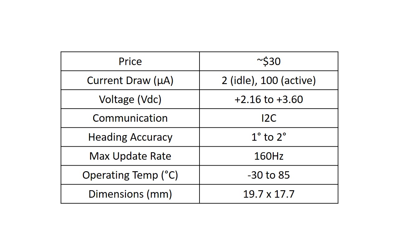
HMC5883L 3-axis magnetometer สามารถวัดขนาดและทิศทางของสนามแม่เหล็กโลกในแนวแกน X, Y และ Z ได้อย่างแม่นยำ ส่งผลให้สามารถนำไปใช้ระบุทิศทางเข็มทิศได้ ซึ่งเป็นเหตุผลว่าทำไมมันถึงถูกเรียกว่า Digital compass อุปกรณ์นี้เป็นอุปกรณ์พลังงานต่ำที่มีขนาดเล็ก (Form factor) ทำให้คุณสามารถนำไปติดตั้งในโปรเจกต์ใดก็ได้ที่ต้องการการระบุทิศทางเข็มทิศ ตารางด้านล่างแสดงรายละเอียดสเปคบางส่วนของ Module นี้
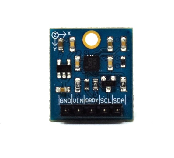
Breakout board จาก Datasheet สำหรับ HMC5883L IC ประกอบด้วย 5 Pin ได้แก่ GND, VIN, DRDY, SCL และ SDA (รูปภาพแสดงอยู่ด้านล่าง) Pin GND และ VIN ใช้สำหรับจ่ายไฟให้อุปกรณ์ แม้ว่า Datasheet ของ Parallax จะระบุว่า Module นี้ทำงานได้ในช่วง 2.7V ถึง 6.5V แต่เราพบปัญหาในการทำให้ Magnetometer ทำงานที่ 5V ดังนั้น เราจึงแนะนำให้ใช้ไฟ 3.3Vdc โดย Pin GND และ VIN จะเชื่อมต่อกับ Pin GND และ 3.3V บน Arduino Uno ตามลำดับ
ในการสื่อสารกับอุปกรณ์ เราใช้ Protocol I2C ซึ่งใช้เพียงสอง Pin คือ SCL และ SDA เราใช้สิ่งนี้เพื่อตั้งค่า Register ต่างๆ บนอุปกรณ์ (เช่น การตั้งค่าโหมดการวัดและอัตราการส่งข้อมูล Output) และเพื่อรับค่าการวัดสนามแม่เหล็กในแกน X, Y และ Z อุปกรณ์นี้มี Address ขนาด 7-bit อยู่ที่ 0x1E เท่านั้น ดังนั้นคุณจึงไม่สามารถมีอุปกรณ์ประเภทนี้มากกว่าหนึ่งตัวบน I2C Bus ในเวลาเดียวกันได้ Pin SCL และ SDA จะเชื่อมต่อกับ Analog Pin A5 และ A4 ของ Arduino Uno ตามลำดับ
Pin DRDY (Data Ready) ใช้เพื่อบอกอุปกรณ์ Master (Arduino Uno) ว่าข้อมูลใน Register X, Y และ Z พร้อมใช้งานแล้ว อัตราการส่งข้อมูลสูงสุดคือ 75Hz แต่เมื่อใช้ Pin DRDY คุณสามารถทำความเร็วได้ถึง 160Hz คุณสามารถเชื่อมต่อ Pin นี้เข้ากับ Interrupt pin บน Arduino Uno เพื่อการรับข้อมูลที่มีประสิทธิภาพ อย่างไรก็ตาม เราจะไม่ได้ใช้ Pin DRDY นี้ในโปรเจกต์นี้
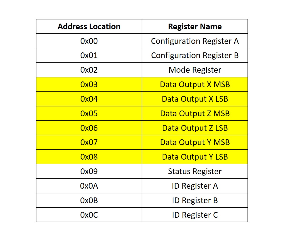
อุปกรณ์นี้มี Magneto-resistive Sensor ในแต่ละแกนจากทั้ง 3 แกนเพื่อวัดสนามแม่เหล็ก เมื่ออยู่ในบริเวณที่มีสนามแม่เหล็ก ความต้านทานขององค์ประกอบเหล่านี้จะเปลี่ยนไป ซึ่งทำให้เกิดการเปลี่ยนแปลงของแรงดันไฟฟ้าที่ Output การเปลี่ยนแปลงแรงดันไฟฟ้านี้จะถูกวัดในแต่ละแกนโดย ADC ขนาด 12-bit ของอุปกรณ์ จากนั้นค่าการวัดจะถูกเขียนลงใน Data register ขนาด 8-bit ของแกน X, Y และ Z ที่เกี่ยวข้อง
ตารางด้านล่างแสดง Address map ของแต่ละ Register โดย Register ที่ไฮไลท์ด้วยสีเหลืองคือ Register ที่เราจะอ่านค่าเพื่อวัดสนามแม่เหล็กในแต่ละแกน หากต้องการทราบรายละเอียดเพิ่มเติมของแต่ละ Register โปรดศึกษาจาก Datasheet ของ HMC5883L IC
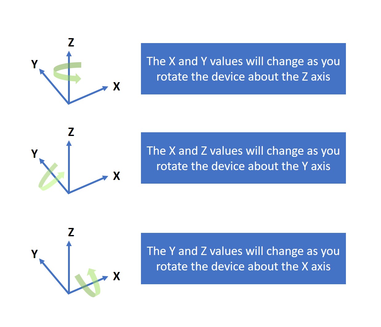
เมื่อคุณหมุนอุปกรณ์รอบแกน X, Y และ Z สนามแม่เหล็กในแต่ละแกนจะเปลี่ยนไป ดังที่แสดงในรูปภาพด้านล่าง อุปกรณ์จะต้องถูกจัดวางโดยให้ระนาบ X-Y (ด้านบนของบอร์ด) ขนานกับพื้นและชี้ขึ้นด้านบน
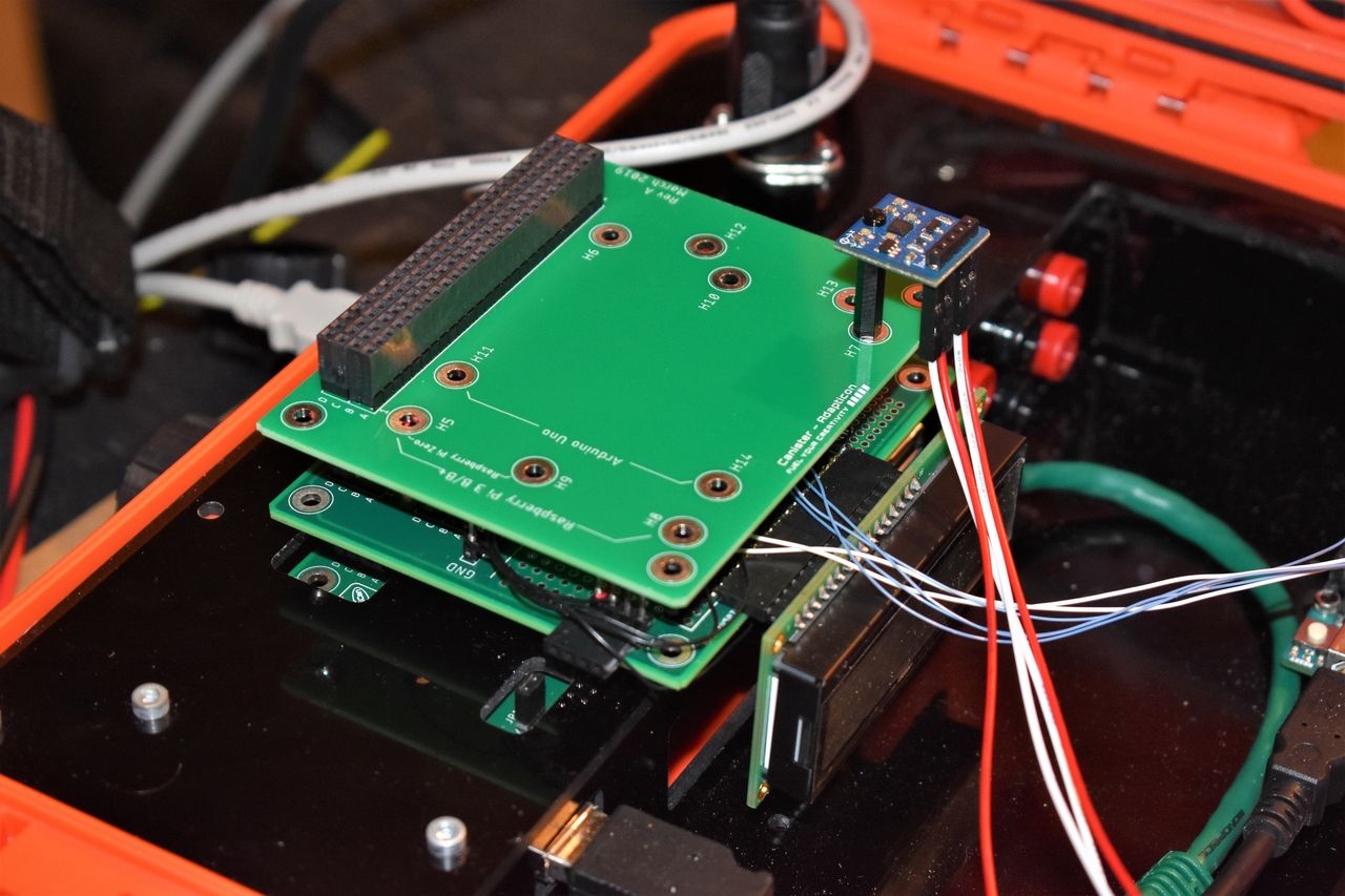
คุณสามารถติดตั้ง Magnetometer เข้ากับ Adapticon เพื่อความมั่นคง คุณจะต้องใช้ Hex standoff ตัวผู้-ตัวเมียขนาด M2, น็อต M2 และสกรู M2 ในการติดตั้ง สิ่งนี้จะช่วยให้ระนาบ X-Y ขนานกับพื้นและช่วยให้คุณสามารถหมุน FuelCan รอบแกน Z เพื่อให้ได้ทิศทางเข็มทิศที่แม่นยำ ตรวจสอบให้แน่ใจว่าได้ใช้ฮาร์ดแวร์ยึดที่เป็นวัสดุที่ไม่ใช่เหล็ก (Non-ferrous) เพื่อหลีกเลี่ยงการรบกวนสนามแม่เหล็ก รูปภาพของ Magnetometer ที่ติดตั้งกับ Adapticon แสดงอยู่ด้านล่าง
เราปล่อยให้อุปกรณ์เชื่อมต่อกับสาย Jumper ยาว 12 นิ้ว เพื่อให้สามารถเคลื่อนย้ายไปมาได้อย่างอิสระทุกทิศทาง
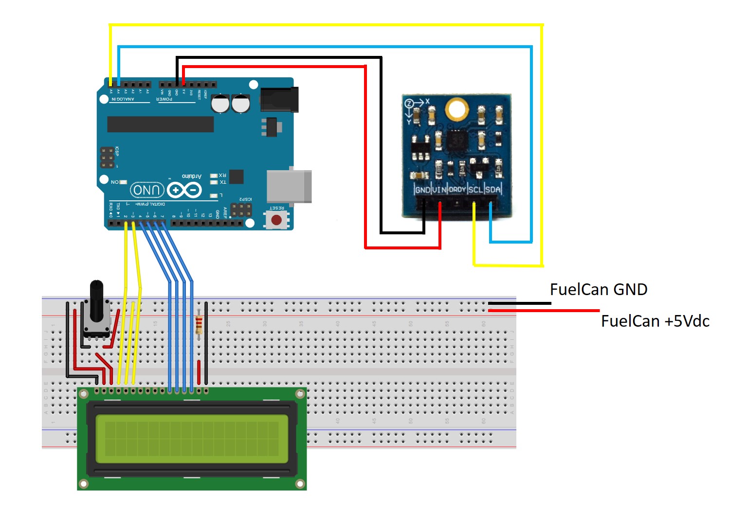
หากคุณใช้ Breadboard แบบไม่มีการบัดกรี ให้ใช้ Schematic ด้านล่างเพื่อทำการเชื่อมต่อที่จำเป็นสำหรับ LCD ขนาด 16x2 โดย Magnetometer จะเชื่อมต่อโดยตรงกับ Arduino Uno ด้วยสาย Jumper แบบ F/M ยาว 12 นิ้ว เราใช้ไฟเลี้ยง 3V3 จาก Arduino Uno แทนที่จะเป็น Rail 3V3 ของ FuelCan เนื่องจากระยะห่าง (Pitch) 0.1 นิ้วของ Male header pins นั้นชิดกันเกินไปที่จะติดตั้งสาย Clip ของ Test-lead ไว้ข้างกัน
หมายเหตุ: Schematic แสดง LCD ขนาด 16x2 แต่ LCD ขนาด 20x4 นั้นมี Pin ที่เข้ากันได้ (Pin compatible) สิ่งเดียวที่คุณต้องเปลี่ยนคือในส่วนของ Software
หากคุณยังไม่ได้ติดตั้ง Arduino Uno ลงในพื้นที่ Prototyping ของ FuelCan ให้ดำเนินการได้เลย หากคุณใช้ Breadboard แทน Modulus ให้วาง Breadboard ไว้ในช่องเก็บของด้านล่างเพื่อจำกัดความยาวของสาย Jumper คุณจะต้องจ่ายไฟ +5V และ GND ไปยัง Power rail และ Ground rail บน Breadboard โดยใช้สาย Banana jack to test-lead clip ที่ให้มา คุณจะต้องใช้ Male header pins สองตัวเพื่อยึดสาย Clip บนฝั่ง Breadboard ซึ่งใช้สำหรับจ่ายไฟให้ LCD
ถัดไป ให้เสียบสาย USB ด้าน Type A เข้ากับช่อง USB1 และด้าน Type B เข้ากับช่องของ Arduino Uno เสียบสาย Type A to Type A ยาว 6 ฟุต โดยปลายด้านหนึ่งเสียบเข้ากับขั้วต่อ USB ภายนอก และปลายอีกด้านหนึ่งเสียบเข้ากับเครื่อง Host (เช่น คอมพิวเตอร์) จากนั้นเปิดเครื่อง FuelCan ด้วย AC-DC power adapter
สำหรับข้อมูลเพิ่มเติมเกี่ยวกับ Fuelcan-910 คลิกที่นี่.
เราสื่อสารกับอุปกรณ์ผ่าน I2C ดังนั้นอย่าลืม include Library Wire.h ก่อนที่เราจะเริ่มรับข้อมูลจากอุปกรณ์ เราต้องกำหนดค่าก่อนโดยใช้ Function setOperatingMode() และ setSamples() เพื่อตั้งค่าโหมดการทำงานเป็นแบบต่อเนื่อง (Continuous) และกำหนดจำนวนตัวอย่างเฉลี่ย (Sample averaging) ต่อหนึ่งการวัดไว้ที่ 8 ส่วนค่าอื่นๆ จะถูกปล่อยไว้เป็นค่าเริ่มต้น (Default)
เมื่อกำหนดค่า Register เรียบร้อยแล้ว เราสามารถเริ่มรับข้อมูลดิบ X, Y และ Z ได้ด้วย Function getXYZ() ซึ่งจะดึงข้อมูลขนาด 16-bit ของ X, Y และ Z ออกมา Function Wire.requestFrom() ภายใน getXYZ() ถูกใช้เพื่อขอรับข้อมูลจำนวน 6 Byte
เมื่อเราได้ค่าดิบ X, Y และ Z แล้ว Function convert() จะถูกเรียกเพื่อแปลงค่าดิบ (Raw count) เป็นหน่วย Gauss (หน่วยที่ใช้ในการวัดสนามแม่เหล็ก) ในการแปลงค่า เราต้องอ้างอิงจาก Table 9 (Gain Settings) ใน Datasheet ของ IC เนื่องจากเราใช้ค่า Gain เริ่มต้น เราจึงใช้ค่า Gain อยู่ที่ 1090 เราสามารถนำค่าดิบมาหารด้วย Gain เพื่อแปลงเป็นหน่วย Gauss ได้ทันที
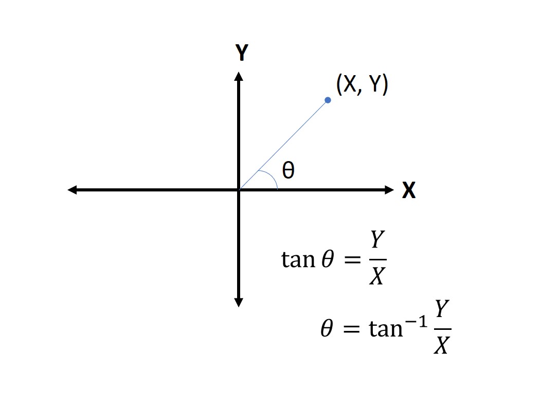
สิ่งสุดท้ายที่ต้องทำก่อนจะแสดงผลข้อมูลผ่าน Serial Monitor คือการคำนวณทิศทาง (Heading) หากอุปกรณ์อยู่ในระนาบ X-Y ขนานกับพื้น เราสามารถใช้ค่า X และ Y เพื่อหา Vector ที่ระบุทิศทางได้ ซึ่งทำได้ด้วย Function getHeading() โดยจะคำนวณค่า Arctangent ระหว่างจุด (X, Y) และแกน X ดังที่แสดงในรูปภาพด้านล่าง สาเหตุที่เราใช้ atan2 คือเพื่อให้สามารถคำนวณ Arctangent ได้ในทั้งสี่ Quadrant
atan2 จะคืนค่ามุมเป็นหน่วย Radians ดังนั้นเราจึงแปลงเป็นหน่วย Degrees (องศา) เข็มทิศจะระบุทิศทางในช่วง 0 ถึง 360 องศาเท่านั้น หากเราได้ค่าอยู่นอกช่วงนี้ เราสามารถบวกเพิ่ม 360 หากค่าติดลบ หรือลบออก 360 หากค่ามากกว่า 360 เมื่อข้อมูลถูกปรับมาตรฐาน (Normalized) และทิศทางถูกคำนวณแล้ว เราสามารถแสดงผลผ่าน Serial Monitor ได้
//Interface a HMC5883L 3-axis digital compass to an Arduino Uno
/*Copyright (c) 2019, ProteShea LLC
All rights reserved.
Redistribution and use in source and binary forms, with or without
modification, are permitted provided that the following conditions are met:
1. Redistributions of source code must retain the above copyright
notice, this list of conditions and the following disclaimer.
2. Redistributions in binary form must reproduce the above copyright
notice, this list of conditions and the following disclaimer in the
documentation and/or other materials provided with the distribution.
3. Neither the name of the copyright holders nor the
names of its contributors may be used to endorse or promote products
derived from this software without specific prior written permission.
THIS SOFTWARE IS PROVIDED BY THE COPYRIGHT HOLDERS ''AS IS'' AND ANY
EXPRESS OR IMPLIED WARRANTIES, INCLUDING, BUT NOT LIMITED TO, THE IMPLIED
WARRANTIES OF MERCHANTABILITY AND FITNESS FOR A PARTICULAR PURPOSE ARE
DISCLAIMED. IN NO EVENT SHALL THE COPYRIGHT HOLDER BE LIABLE FOR ANY
DIRECT, INDIRECT, INCIDENTAL, SPECIAL, EXEMPLARY, OR CONSEQUENTIAL DAMAGES
(INCLUDING, BUT NOT LIMITED TO, PROCUREMENT OF SUBSTITUTE GOODS OR SERVICES;
LOSS OF USE, DATA, OR PROFITS; OR BUSINESS INTERRUPTION) HOWEVER CAUSED AND
ON ANY THEORY OF LIABILITY, WHETHER IN CONTRACT, STRICT LIABILITY, OR TORT
(INCLUDING NEGLIGENCE OR OTHERWISE) ARISING IN ANY WAY OUT OF THE USE OF THIS
SOFTWARE, EVEN IF ADVISED OF THE POSSIBILITY OF SUCH DAMAGE.
*/
#include
#define configA 0x00
#define configB 0x01
#define mode 0x02
#define dataOutX_U 0x03
#define dataOutX_L 0x04
#define dataOutZ_L 0x05
#define dataOutZ_L 0x06
#define dataOutY_L 0x07
#define dataOutY_L 0x08
#define statusReg 0x09
//Operating modes sent to Mode register (0x02)
#define continuous 0x00
#define single 0x01
#define idle 0x02
#define i2c_addr 0x1E
#define gain 1090
int16_t x = 0;
int16_t y = 0;
int16_t z = 0;
float heading;
float gaussX;
float gaussY;
float gaussZ;
void setup() {
Wire.begin();
Serial.begin(9600);
setOperatingMode(continuous);
setSamples();
}
void loop() {
getXYZ();
convert(x,y,z);
getHeading(gaussX,gaussY,gaussZ);
Serial.print("X: ");
Serial.print(gaussX);
Serial.print(" Y: ");
Serial.print(gaussY);
Serial.print(" Z: ");
Serial.println(gaussZ);
Serial.print("Heading: ");
Serial.println(heading);
delay(500);
}
//Convert the raw X, Y, Z counts to Gauss
void convert(int16_t rawX, int16_t rawY, int16_t rawZ){
gaussX = (float)rawX/gain;
gaussY = (float)rawY/gain;
gaussZ = (float)rawZ/gain;
}
//accounts for declination (error in magnetic field which is dependent on location)
void getHeading(float X, float Y, float Z){
heading = (atan2(Y,X) - 0.1) * 180 / PI;
if (heading < 0) heading += 360;
if (heading > 360) heading -= 360;
}
void setSamples(void){
Wire.beginTransmission(i2c_addr);
Wire.write(configA); //write to config A register
Wire.write(0x70); //8 samples averaged, 15Hz output rate, normal measurement
Wire.endTransmission();
delay(10);
}
void setOperatingMode(uint8_t addr){
Wire.beginTransmission(i2c_addr);
Wire.write(mode); //write to mode register
Wire.write(addr); //set measurement mode
Wire.endTransmission();
delay(10);
}
//get the raw counts of X, Y, Z from registers 0x03 to 0x08
void getXYZ(void){
Wire.beginTransmission(i2c_addr);
Wire.write(0x03);
Wire.endTransmission();
Wire.requestFrom(i2c_addr, 6);
if (Wire.available() >= 6){
int16_t temp = Wire.read(); //read upper byte of X
x = temp << 8;
temp = Wire.read(); //read lower byte of X
x = x | temp;
temp = Wire.read(); //read upper byte of Z
z = temp << 8;
temp = Wire.read(); //read lower byte of Z
z = z | temp;
temp = Wire.read(); //read upper byte of Y
y = temp << 8;
temp = Wire.read(); //read lower byte of Y
y = y | temp;
}
}
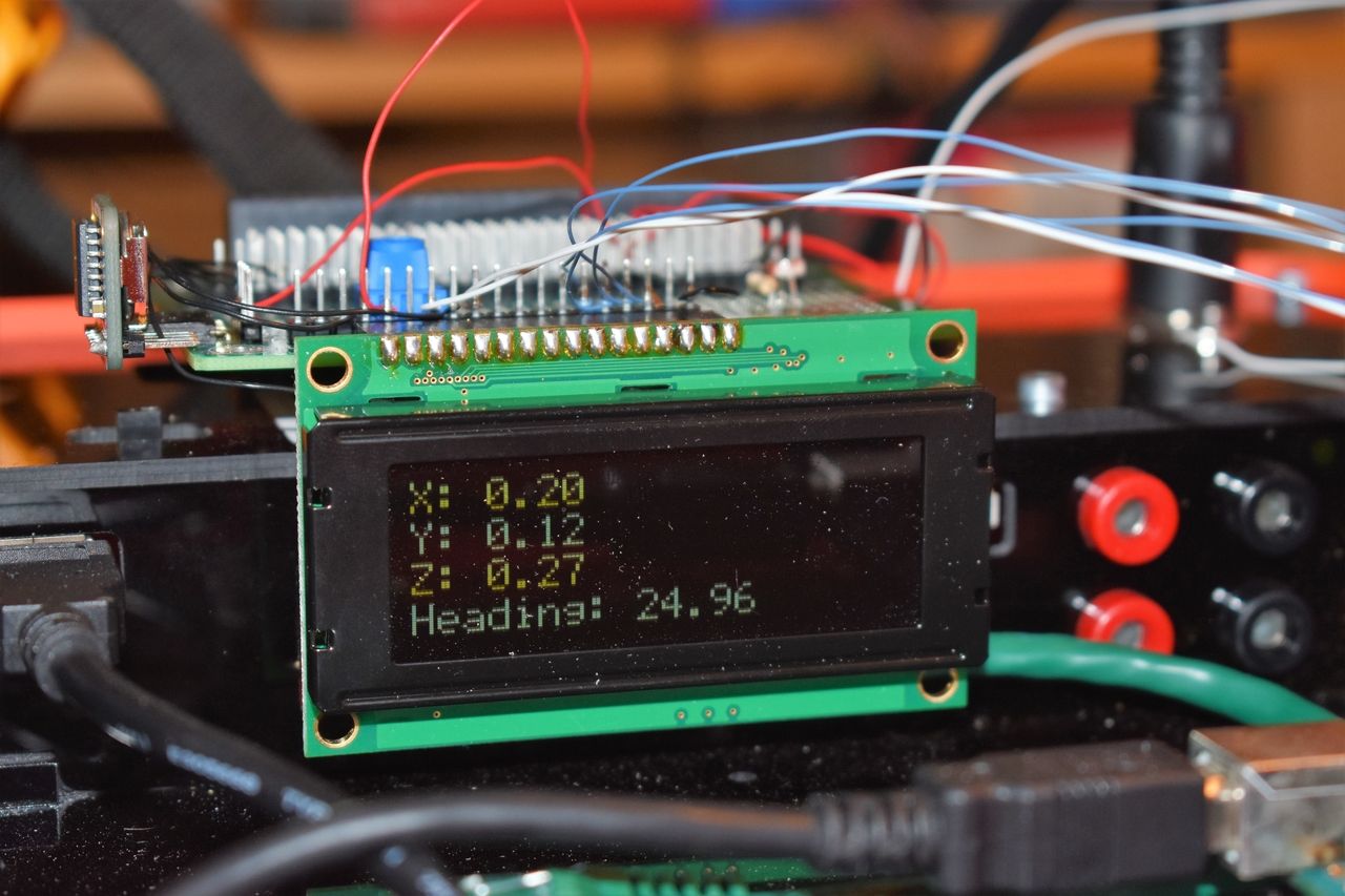
ตัวอย่างถัดไปคือการแสดงผลข้อมูลบน LCD ขนาด 20x4 โดยการเรียก Function writeLCD()

//Interface a HMC5883L 3-axis digital compass to an Arduino Uno and display
//data on 20x4 LCD
/*Copyright (c) 2019, ProteShea LLC
All rights reserved.
Redistribution and use in source and binary forms, with or without
modification, are permitted provided that the following conditions are met:
1. Redistributions of source code must retain the above copyright
notice, this list of conditions and the following disclaimer.
2. Redistributions in binary form must reproduce the above copyright
notice, this list of conditions and the following disclaimer in the
documentation and/or other materials provided with the distribution.
3. Neither the name of the copyright holders nor the
names of its contributors may be used to endorse or promote products
derived from this software without specific prior written permission.
THIS SOFTWARE IS PROVIDED BY THE COPYRIGHT HOLDERS ''AS IS'' AND ANY
EXPRESS OR IMPLIED WARRANTIES, INCLUDING, BUT NOT LIMITED TO, THE IMPLIED
WARRANTIES OF MERCHANTABILITY AND FITNESS FOR A PARTICULAR PURPOSE ARE
DISCLAIMED. IN NO EVENT SHALL THE COPYRIGHT HOLDER BE LIABLE FOR ANY
DIRECT, INDIRECT, INCIDENTAL, SPECIAL, EXEMPLARY, OR CONSEQUENTIAL DAMAGES
(INCLUDING, BUT NOT LIMITED TO, PROCUREMENT OF SUBSTITUTE GOODS OR SERVICES;
LOSS OF USE, DATA, OR PROFITS; OR BUSINESS INTERRUPTION) HOWEVER CAUSED AND
ON ANY THEORY OF LIABILITY, WHETHER IN CONTRACT, STRICT LIABILITY, OR TORT
(INCLUDING NEGLIGENCE OR OTHERWISE) ARISING IN ANY WAY OUT OF THE USE OF THIS
SOFTWARE, EVEN IF ADVISED OF THE POSSIBILITY OF SUCH DAMAGE.
*/
#include
#define configA 0x00
#define configB 0x01
#define mode 0x02
#define dataOutX_U 0x03
#define dataOutX_L 0x04
#define dataOutZ_L 0x05
#define dataOutZ_L 0x06
#define dataOutY_L 0x07
#define dataOutY_L 0x08
#define statusReg 0x09
//Operating modes sent to Mode register (0x02)
#define continuous 0x00
#define single 0x01
#define idle 0x02
#define i2c_addr 0x1E
#define gain 1090
const int RS = 2, EN = 3, D4 = 4, D5 = 5, D6 = 6, D7 = 7;
LiquidCrystal lcd(RS,EN,D4,D5,D6,D7); //set Uno pins that are connected to LCD, 4-bit mode
int16_t x = 0;
int16_t y = 0;
int16_t z = 0;
float heading;
float gaussX;
float gaussY;
float gaussZ;
void setup() {
Wire.begin();
lcd.begin(20,4); //set 20 columns and 4 rows of 20x4 LCD
setOperatingMode(continuous);
setSamples();
}
void loop() {
getXYZ();
convert(x,y,z);
getHeading(gaussX,gaussY,gaussZ);
writeLCD();
delay(500);
}
void writeLCD(void){
lcd.clear();
lcd.print("X: ");
lcd.print(gaussX);
lcd.setCursor(0,1);
lcd.print("Y: ");
lcd.print(gaussY);
lcd.setCursor(0,2);
lcd.print("Z: ");
lcd.print(gaussZ);
lcd.setCursor(0,3);
lcd.print("Heading: ");
lcd.print(heading);
}
//Convert the raw X, Y, Z counts to Gauss
void convert(int16_t rawX, int16_t rawY, int16_t rawZ){
gaussX = (float)rawX/gain;
gaussY = (float)rawY/gain;
gaussZ = (float)rawZ/gain;
}
//accounts for declination (error in magnetic field which is dependent on location)
void getHeading(float X, float Y, float Z){
heading = (atan2(Y,X) - 0.1) * 180 / PI;
if (heading < 0) heading += 360;
if (heading > 360) heading -= 360;
}
void setSamples(void){
Wire.beginTransmission(i2c_addr);
Wire.write(configA); //write to config A register
Wire.write(0x70); //8 samples averaged, 15Hz output rate, normal measurement
Wire.endTransmission();
delay(10);
}
void setOperatingMode(uint8_t addr){
Wire.beginTransmission(i2c_addr);
Wire.write(mode); //write to mode register
Wire.write(addr); //set measurement mode
Wire.endTransmission();
delay(10);
}
//get the raw counts of X, Y, Z from registers 0x03 to 0x08
void getXYZ(void){
Wire.beginTransmission(i2c_addr);
Wire.write(0x03);
Wire.endTransmission();
Wire.requestFrom(i2c_addr, 6);
if (Wire.available() >= 6){
int16_t temp = Wire.read(); //read upper byte of X
x = temp << 8;
temp = Wire.read(); //read lower byte of X
x = x | temp;
temp = Wire.read(); //read upper byte of Z
z = temp << 8;
temp = Wire.read(); //read lower byte of Z
z = z | temp;
temp = Wire.read(); //read upper byte of Y
y = temp << 8;
temp = Wire.read(); //read lower byte of Y
y = y | temp;
}
}
สนับสนุนเพื่อรับ Source Code หรือแอปพลิเคชันสำหรับโปรเจกต์นี้
ประเมิน Project
เอาฟอร์มยาวออกจากท้ายหน้า Project แล้ว เหลือเป็นปุ่มให้กดไปกรอกหน้าเดียว ตัวใหญ่ เว้นบรรทัดเยอะ อ่านง่ายกว่า
รีวิวจากคนใช้งานจริง
ถ้าเคยสั่งงาน เคยอ่านหน้านี้แล้วได้ประโยชน์ หรือมีข้อเสนอแนะ ฝากรีวิวไว้ได้เลย
ยังไม่มีรีวิวบนหน้านี้ ถ้าเคยใช้งานหรือมีข้อเสนอแนะ เขียนเป็นคนแรกได้เลย