Intermediate
Arduino IoT Based Energy Meter
Monitor your energy consumption through the Arduino IoT Cloud using a MKR WiFi 1010, a MKR 485 Shield and a Modbus compatible energy meter.

Monitor your energy consumption through the Arduino IoT Cloud using a MKR WiFi 1010, a MKR 485 Shield and a Modbus compatible energy meter.
Project Supporter Team
Posted by
In this tutorial, we will show you how to create an energy meter which allows you to track your energy consumption through the Arduino IoT Cloud. Regardless of whether you want to save energy, automate your home accordingly or simply become more aware of your consumption, measuring your electricity consumption is a good idea.
This tutorial provides a step-by-step explanation of how to set up your new energy meter, using the widely used Modbus protocol to monitor your data. If you are new to the topic, we recommend you read our article on Modbus before getting started. For those who are already familiar with Modbus and have used it before simply follow the steps in the following sections.
This project is dealing with high voltages that can result in serious harm! We advise you to check with your electrician before continuing with this project!
The standard mounting system for electrical equipment is DIN rail which can be found in most fuse boxes. Simply download the template provided in this tutorial to 3D print your enclosure for both your MKR WiFi 1010 and your MKR 485 Shield.
Step 1 Assemble the Enclosure
Download the files and print both the cable clamp and the accompanying lid. Put the MKR 485 Shield on top of the MKR WiFi 1010 and place both of them inside the case. There are small nobs for each of the four holes found on the MKR boards to keep everything in place.
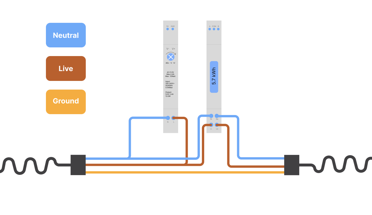
Step2 Connect the energy meter and the power supply
Note that the colour code for electrical wiring is dependent on your location and it is important that you check the specification for your country!
The next step is to connect the live wire and the neutral wire to the energy meter and the power supply as shown below:
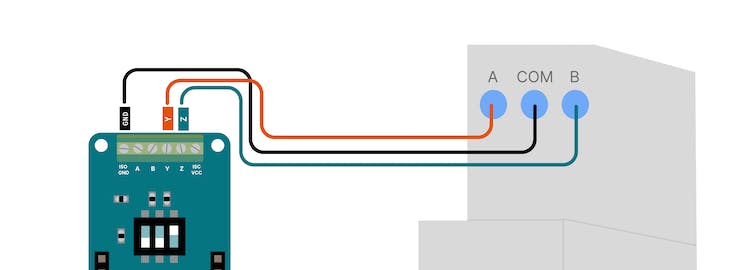
Step3 Connect the MKR 485 Shield
The MKR 485 Shield has three little switches with numbers from 1 to 3. Make sure to set them to the following position:
If you want to learn more about how Modbus communication via RS485 works check out this tutorial.
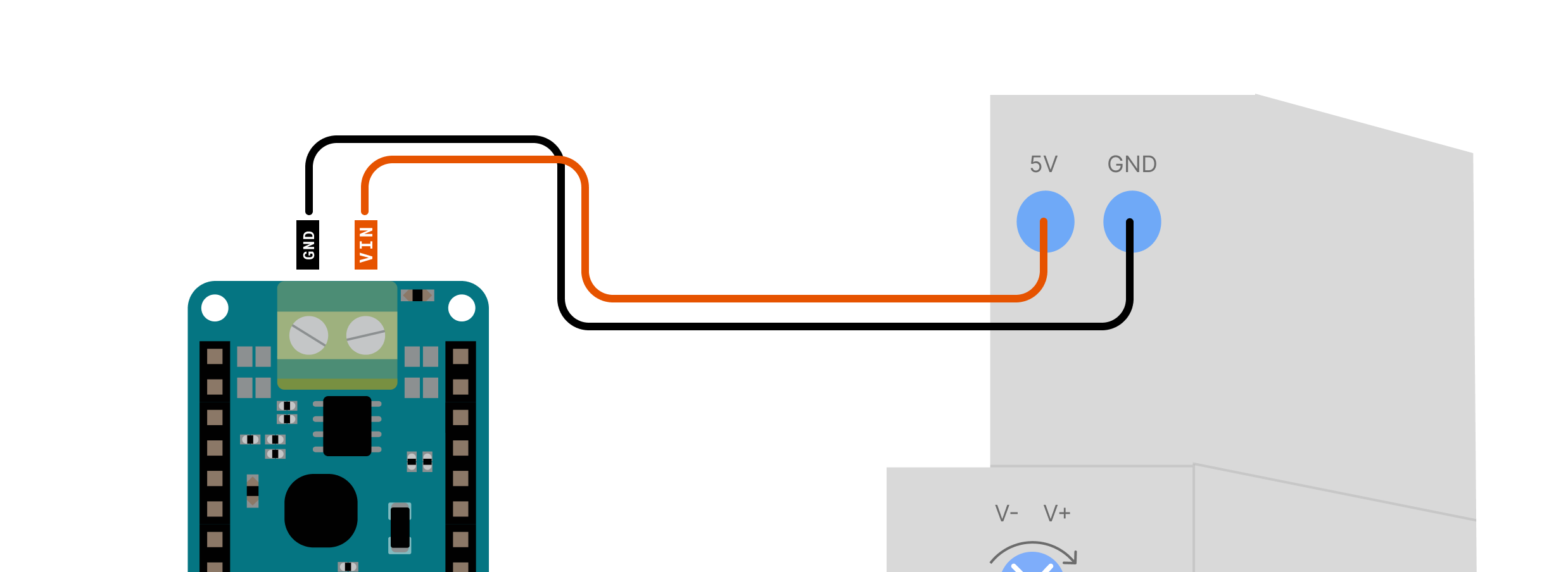
To power our setup we will connect 5V and GND from the power supply to the back of the MKR 485 Shield as shown below:
Setup
Now it is time to set up the Arduino IoT Cloud. If you have never used the Cloud before just follow this quick tutorial to add your board and connect it to the WiFi network.
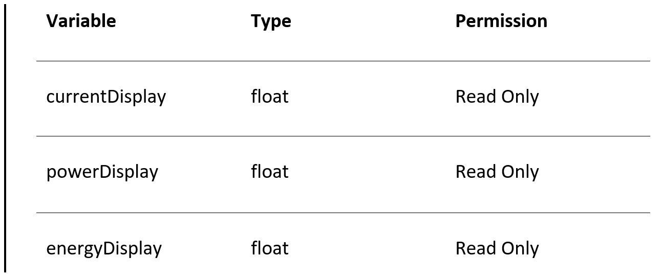
Variables
After setting up your board you need to add three variables:
Code
Copy and upload the code from here.
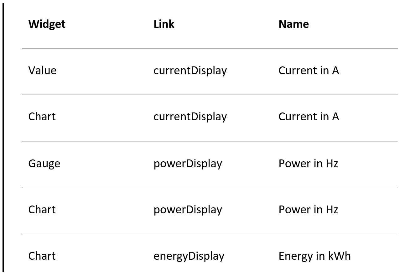
Dashboard
Create a new dashboard and add these widgets:
Outcome
You should see something like this
You have now created your own Arduino IoT Cloud-based energy meter! If you want to expand this setup or hook it up to your existing Arduino automations systems check out our Arduino IoT Cloud subscription plans to unleash its full potential.
Support to get the Source Code for this project
Project estimate
The long estimate form has moved to a separate page so this project page stays clean.
รีวิวจากคนใช้งานจริง
ถ้าเคยสั่งงาน เคยอ่านหน้านี้แล้วได้ประโยชน์ หรือมีข้อเสนอแนะ ฝากรีวิวไว้ได้เลย
ยังไม่มีรีวิวบนหน้านี้ ถ้าเคยใช้งานหรือมีข้อเสนอแนะ เขียนเป็นคนแรกได้เลย