Intermediate
โปรเจกต์ เริ่มต้นใช้งาน OLED Displays
OLED คือ Diode ประเภทหนึ่งที่ประกอบด้วย Organic compound ซึ่งจะส่องสว่างเมื่อมี Current ไหลผ่าน

OLED คือ Diode ประเภทหนึ่งที่ประกอบด้วย Organic compound ซึ่งจะส่องสว่างเมื่อมี Current ไหลผ่าน

▶ กดเพื่อดูวิดีโอสาธิตโปรเจกต์
OLED คือไดโอดชนิดหนึ่งที่ประกอบด้วยสารประกอบอินทรีย์ที่สามารถส่องสว่างได้เมื่อมีกระแสไฟฟ้าไหลผ่าน
วิธีที่ OLED สื่อสารกับ Arduino คือผ่านทาง Inter-Integrated Circuit (I2C) อย่างไรก็ตาม ยังสามารถสื่อสารผ่าน Serial Peripheral Interface (SPI) ได้เช่นกัน สำหรับบทเรียนนี้ เราจะเน้นไปที่การสื่อสารแบบ I2C ซึ่งการสื่อสารประเภทนี้ช่วยให้ Slave หลายตัวสามารถสื่อสารกับ Master ตัวเดียวได้ ในกรณีนี้ เราจะทำงานกับ Slave เพียงตัวเดียวคือชิป SSD1306 โดยมี Master คือ Arduino UNO
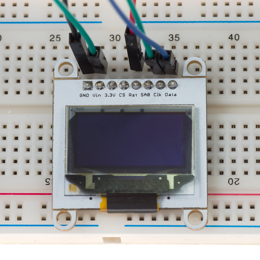
SSD1306 เป็นชิปเดี่ยว CMOS OLED/PLED driver พร้อมคอนโทรลเลอร์สำหรับระบบแสดงผลกราฟิก dot-matrix ของไดโอดเปล่งแสงแบบสารประกอบอินทรีย์/โพลิเมอร์ พูดง่ายๆ ก็คือมันเป็นอุปกรณ์ที่ทำหน้าที่ควบคุมหน้าจอโดยสั่งการให้หน้าจอทำงานต่างๆ ในการสร้างการสื่อสารแบบ I2C ระหว่าง Master และ Slave จำเป็นต้องใช้เพียงสองช่องทางคือ SDA และ CLK อย่างไรก็ตาม เรายังต้องคำนึงถึง VCC และ Ground สำหรับการจ่ายแรงดันไฟฟ้า และในกรณีนี้มี RST สำหรับการเริ่มต้นระบบ (initialization) ด้วย ภาพด้านล่างแสดงการต่อสายไฟสำหรับ OLED ของเรา:

SDA ทำหน้าที่ในการส่งข้อมูลและตรงกับ Pin A4 ใน Arduino ส่วน CLK ทำหน้าที่กำหนดสัญญาณนาฬิกาเพื่อการซิงโครไนซ์ และตรงกับ Pin A5 ใน Arduino อย่างไรก็ตาม Pin เหล่านี้จะเปลี่ยนไปหากคุณไม่ได้ใช้ Arduino UNO หรือ Ethernet สามารถดูลิงก์ด้านล่างเพื่อตรวจสอบ I2C Pins สำหรับ Arduino รุ่นต่างๆ: https://www.arduino.cc/en/Reference/Wire
RST ใช้เพื่อรีเซ็ตอุปกรณ์กลับไปเป็นค่าเริ่มต้น และสามารถต่อเข้ากับ Digital Input ช่องใดก็ได้ใน Arduino ในกรณีนี้เราใช้ Pin 10 เมื่อกำหนดช่องทางสำหรับการสื่อสารเรียบร้อยแล้ว ก็จะสามารถส่งข้อมูลไปยังอุปกรณ์ของเราได้ รูปที่ 1 แสดงวิธีการดำเนินการดังกล่าว
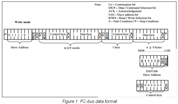
สิ่งแรกที่เราต้องการคือ Slave address เลขเจ็ดหลักนี้จะระบุตัวตนของอุปกรณ์เฉพาะอย่าง เพื่อให้ Master รู้ว่าต้องการสื่อสารกับ Slave ตัวไหน จาก datasheet ของ SSD1306 ค่า Slave address สำหรับไดรเวอร์นี้อาจเป็น “0111100” หรือ “0111101” ขึ้นอยู่กับ SA0 (ว่าเป็น high หรือ low) โดยค่าเริ่มต้นจะเป็น high แต่ถ้าคุณต้องการเปลี่ยน Slave address คุณสามารถต่อสาย SA0 เข้ากับ Digital Pin ใดก็ได้ใน Arduino และตั้งค่าเป็นศูนย์ ในบทเรียนนี้ เราตัดสินใจที่จะไม่เปลี่ยน SA0 ดังนั้น Address ของ Slave ของเราคือ 0x3D เนื่องจาก OLED จะอยู่ในโหมดเขียนเสมอ Bit R/W# (read/write bit) จึงถูกตั้งค่าเป็น “0”
สิ่งต่อไปที่เราต้องการคือ Control byte ซึ่งกำหนดโดย Co (continuation bit) และ D/C# (data/command selection bit) ตามด้วย “0” จำนวนหกตัว Co จะกำหนดว่า Byte ถัดไปจะเป็น Byte เดียวหรือเป็น Stream ของข้อมูล ในขณะที่ D/C# จะกำหนดว่า Byte นั้นจะถูกจัดการในฐานะข้อมูล (Data) หรือคำสั่ง (Command) ดังนั้นเราจึงมี Control byte ที่เป็นไปได้สี่แบบ ดังนี้:
คุณสามารถดูรายการคำสั่งทั้งหมดได้ในตารางที่ 9-1 ใน datasheet ของ SSD1306
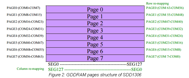
OLED ประกอบด้วย 128 คอลัมน์ (SEG) และ 8 หน้า (Page) ซึ่งแต่ละหน้าประกอบด้วย 8 แถว (COM) ดังที่แสดงในรูปที่ 2
ในขณะที่คำสั่งถูกใช้เพื่อกำหนดค่าหน้าจอและปรับแต่งผ่านการใช้ Registers แต่ข้อมูล (Data) จะถูกใช้เพื่อแสดงผลข้อมูลใดก็ตามที่เก็บไว้ใน GDDRAM (Graphic Display Data RAM) หากเราเขียน Byte “00000001” Pixel แรกที่อยู่มุมบนซ้าย หรือที่ Page 0 คอลัมน์ 0 จะสว่างขึ้น สาเหตุที่ Byte ถูกเขียนในลำดับย้อนกลับเป็นเพราะ OLED ใช้การกำหนดค่าต่อไปนี้ในการแสดงผลข้อมูล:
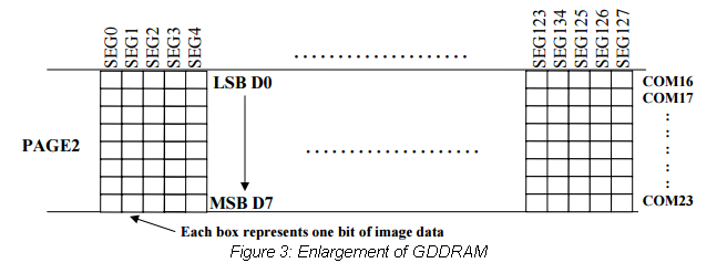
ด้วยการใช้ Pointer ข้อมูลจะเริ่มเติมลงในคอลัมน์ตั้งแต่ Least significant bit ไปจนถึง Most significant bit เมื่อ Pointer ไปถึงจุดสิ้นสุดของคอลัมน์ มันจะเลื่อนไปยังคอลัมน์ถัดไปโดยอัตโนมัติในโหมด Horizontal addressing หรือไปยังหน้าถัดไปในโหมด Vertical addressing (อ้างอิงจาก datasheet ของ SSD1306 สำหรับโหมดการระบุตำแหน่ง)
วิธีวาด Pixel?
ตอนนี้เราทราบวิธีทำงานของ OLED แล้ว เราสามารถสร้างโปรแกรมที่ให้ผู้ใช้สั่งเปิด Pixel เฉพาะจุดบนหน้าจอได้
#include<Wire.h> //Include Wire library for I2C communication
#define HEIGHT 64
#define WIDTH 128
const int RST = 10; //Assign pin 10 for Reset
int i; //Set variable i as integer
static unsigned char array[1024]; //buffer array/>

void setup() {
  pin_init(); //Initialize pins
  initialize_OLED(); //Initialize screen
  memset(array, 0, sizeof(array)); //Clear array
  draw_pixel(63,31); //Store pixel at (x,y) location
  Flush(); //Send data
}

void loop() {
  //Nothing happens here
}

void pin_init(){
  Serial.begin(9600); //Set baud for serial transmission
  pinMode(RST, OUTPUT); //Set RST as output
}

void initialize_OLED(){
  Wire.begin(); //Initialize I2C interface
  digitalWrite(RST, LOW); //Set reset pin low (active)
  delay(10); //Wait 100 ms
  digitalWrite(RST, HIGH); //Set reset pin high (inactive)
  Wire.beginTransmission(0x3D); // Start communication with slave
  Wire.write(0x00); //Command stream
  Wire.write(0xAE); //Set display Off
  Wire.write(0xD5); //Set display clock divide ratio/oscillator frequency
  Wire.write(0x80);
  Wire.write(0xA8); //Set multiplex ratio
  Wire.write(0x3F);
  Wire.write(0xD3); //Set display offset
  Wire.write(0x00);
  Wire.write(0x40); //Set display start line
  Wire.write(0x8D); //Set charge pump
  Wire.write(0x14); //VCC generated by internal DC/DC circuit
  Wire.write(0xA1); //Set segment re-map
  Wire.write(0xC0); //Set COM output scan direction
  Wire.write(0xDA); //Set COM pins hardware configuration
  Wire.write(0x12);
  Wire.write(0x81); //Set contrast control
  Wire.write(0xCF);
  Wire.write(0xD9); //Set pre-changed period
  Wire.write(0xF1);
  Wire.write(0xDB); //Set VCOMH Deselected level
  Wire.write(0x40);
  Wire.write(0xA4); //Set entire display on/off
  Wire.write(0xA6); //Set normal display
  Wire.write(0x20); //Set memory address mode
  Wire.write(0x00); //Horizontal
  Wire.write(0xAF); //Set display on
  Wire.endTransmission(); //End communicaiton with slave
}

void draw_pixel(int x, int y)
  if((x<0) || (x>=WIDTH) || (y<0) || (y>=HEIGHT)){ //Check for boundaries
    return;
  }
  else{
    array[x+(y/8)*WIDTH] |= _BV((y%8)); //Store pixel in array
  }
}

void Flush(){
 Wire.beginTransmission(0x3D); //Start communication with slave
 Wire.write(0x00); //Command stream
 Wire.write(0x00); //Set lower column start address for page addressing mode
 Wire.write(0x10); //Set higher column start address for page addressing mode
 Wire.write(0x40); //Set display start line
 Wire.endTransmission(); //End communication with slave

 unsigned char twbrbackup = TWBR; //Two wire bit rate register
 TWBR = 12; //Set to 400 kHz

 for(unsigned short q=0; q<(WIDTH*HEIGHT/8); q++){
 Wire.beginTransmission(0x3D); //Start communication with slave
 Wire.write(0x40); //Data stream
 for(unsigned char w=0; w<16; w++){
    Wire.write(array[q]); //Transmit data to be displayed
    q++;
 }
 q--;
  Wire.endTransmission(); //End communication with slave
}
TWBR = twbrbackup;
}
Library Wire ช่วยให้ Arduino สามารถสื่อสารกับอุปกรณ์ I2C ได้ ในส่วนแรกของโค้ด เรากำหนด Digital Pin ที่กล่าวไปแล้วให้กับ RST และสร้าง Array เพื่อพักข้อมูล (buffer) ที่เราต้องการแสดงผล จากนั้น Pin RST จะถูกกำหนดค่าเริ่มต้นให้เป็น Output ต่อมา OLED จะถูกกำหนดค่าเริ่มต้นโดยทำตามตัวอย่างที่แสดงใน datasheet ของหน้าจอในหน้า 15 แนะนำให้คุณรีเซ็ตอุปกรณ์หนึ่งครั้งก่อนเริ่มใช้งาน โดยการตั้งค่า RST เป็น low ชั่วขณะหนึ่งแล้วจึงตั้งเป็น high เนื่องจาก Pin นี้ทำงานแบบ active low จึงต้องมีสถานะเป็น high ในระหว่างการทำงานปกติ
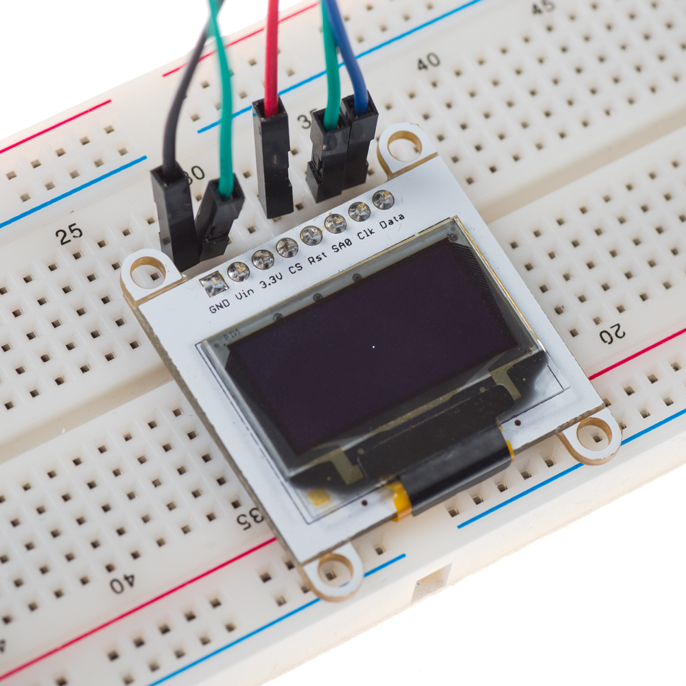
จากนั้นฟังก์ชัน “pixel” จะถูกสร้างขึ้นเพื่อเก็บ Pixel ไว้ในตำแหน่งเฉพาะใน Array buffer ฟังก์ชันนี้รับพารามิเตอร์สองตัวคือ x และ y เพื่อระบุพิกัดที่แม่นยำของจุดที่เราต้องการให้ Pixel แสดงผล โดย x สามารถมีค่าได้ตั้งแต่ 0-127 และ y มีค่าได้ตั้งแต่ 0-63 พิกัด (0,0) จะอยู่ที่ด้านล่างซ้ายของหน้าจอ หากพิกัดอยู่นอกช่วง โปรแกรมจะไม่แสดงผลใดๆ สุดท้าย ฟังก์ชัน “Flush” จะถูกใช้เพื่อแสดงผลองค์ประกอบใน Array buffer โดยส่งข้อมูลแบบ 16 byte burst transfers ในขณะที่โปรแกรมวิ่งผ่าน Buffer ทั้งหมด ภายในฟังก์ชันนี้ TWBR (Two wire bit rate register) ถูกตั้งค่าเป็น 12 เพื่อเพิ่มความถี่ของสัญญาณนาฬิกา Arduino (SCL) จาก 100kHz เป็น 400kHz วิธีนี้จะทำให้การส่งข้อมูลเร็วขึ้น ด้านล่างนี้คือวิธีการคำนวณค่า 12: โดยที่:
สำหรับบทเรียนนี้ เราเลือกพิกัด (63,31) เพื่อเปิด Pixel ที่อยู่ตรงกลางหน้าจอดังที่แสดงในภาพด้านล่าง:
เมื่อเรามีฟังก์ชัน Pixel แล้ว เราสามารถใช้มันเพื่อวาดเส้นตรงที่กำหนดโดยจุดเริ่มต้นและจุดสิ้นสุดบนแกน x และ y บนหน้าจอได้
#include<Wire.h> //Include Wire library for I2C communication
#define HEIGHT 64
#define WIDTH 128
const int RST = 10; //Assign pin 10 for Reset
int i; //Set variable i as integer
static unsigned char array[1024]; //Buffer array

void setup() {
  pin_init(); //Initialize pins
  initialize_OLED(); //Initialize screen
  memset(array, 0, sizeof(array)); //Initialize array with 0s
  line(0,63,0,31); //Draw line
  Flush(); //Send data
}

void loop() {
}

void pin_init(){
  Serial.begin(9600); //Set baud for serial transmission
  pinMode(RST, OUTPUT); //Set RST as output
}

void initialize_OLED(){
  Wire.begin(); //Initialize I2C interface
  digitalWrite(RST, LOW); //Set RST pin low
  delay(100); //Wait 100 ms
  digitalWrite(RST, HIGH); //Set RST pin high
  Wire.beginTransmission(0x3D); // Start communication with slave
  Wire.write(0x00); //Command stream
  Wire.write(0xAE); //Set display Off
  Wire.write(0xD5); //Set display clock divide ratio/oscillator frequency
  Wire.write(0x80);
  Wire.write(0xA8); //Set multiplex ratio
  Wire.write(0x3F);
  Wire.write(0xD3); //Set display offset
  Wire.write(0x00);
  Wire.write(0x40); //Set display start line
  Wire.write(0x8D); //Set charge pump
  Wire.write(0x14); //VCC generated by internal DC/DC circuit
  Wire.write(0xA1); //Set segment re-map
  Wire.write(0xC0); //Set COM output scan direction
  Wire.write(0xDA); //Set COM pins hardware configuration
  Wire.write(0x12);
  Wire.write(0x81); //Set contrast control
  Wire.write(0xCF);
  Wire.write(0xD9); //Set pre-changed period
  Wire.write(0xF1);
  Wire.write(0xDB); //Set VCOMH Deselected level
  Wire.write(0x40);
  Wire.write(0xA4); //Set entire display on/off
  Wire.write(0xA6); //Set normal/inverse display
  Wire.write(0x20); //Set memory address mode
  Wire.write(0x00); //Horizontal
  Wire.write(0xAF); //Set display on
  Wire.endTransmission(); //End communicaiton with slave
}

/*Bresenham's line drawing algorithm*/

void line(int x1, int x2, int y1, int y2){
  int cx = x1;
  int cy = y1;

  int dx = x2-cx;
  int dy = y2-cy;

  if(dx<0){
   dx = 0-dx;
  }
  if(dy<0){
    dy = 0-dy;
  }

  int sx = 0;
  int sy = 0;
  if(cx<x2){
   sx = 1;
  }
  else{
   sx = -1;
  }
  if(cy<y2){
   sy = 1;
  }
  else{
   sy = -1;
  }
  int err = dx-dy;

  for(int n=0; n<1000; n++){
   draw_pixel(cx,cy);
  if((cx==x2) && (cy==y2)){
   return;
  }
  int e2 =2*err;
  if(e2>(0-dy)){
   err = err-dy;
   cx = cx+sx;
  }
  if(e2<dx){
   err = err+dx;
   cy = cy+sy;
   }
  }
 }

void draw_pixel(int x, int y){
  if((x<0) || (x>=WIDTH) || (y<0) || (y>=HEIGHT)){ //Check for boundaries
    return;
  }
  else{
    array[x+(y/8)*WIDTH] |= _BV((y%8)); //Store pixel in array
  }
}

void Flush(){
 Wire.beginTransmission(0x3D); //Start communication with slave
 Wire.write(0x00); //Command stream
 Wire.write(0x00);  //Set lower column start address for page addressing mode
 Wire.write(0x10); //Set higher column start address for page addressing mode
 Wire.write(0x40); //Set display start line
 Wire.endTransmission(); //End communication with slave

 unsigned char twbrbackup = TWBR; //Two wire bit rate register
 TWBR = 12; //Set to 400 kHz

 for(unsigned short q=0; q<(WIDTH*HEIGHT/8); q++){
 Wire.beginTransmission(0x3D); //Start communication with slave
 Wire.write(0x40); //Data stream
 for(unsigned char w=0; w<16; w++){
    Wire.write(array[q]); //Transmit data to be displayed
    q++;
 }
 q--;
  Wire.endTransmission(); //End communication with slave
}
TWBR = twbrbackup;
}
ฟังก์ชันวาดเส้นตรงอ้างอิงจาก Bresenham's Line Drawing Algorithm ที่ใช้สำหรับวาดเส้นด้วย Pixel โปรแกรมของเราได้นำอัลกอริทึมนี้มาใช้งานโดยใช้ Pseudo code ต่อไปนี้: http://41j.com/blog/2012/09/bresenhams-line-drawing-algorithm-implemetations-in-go-and-c/
อัลกอริทึมนี้พื้นฐานแล้วจะเติม Pixel ระหว่าง (x0,y0) และ (x1,y1) โดยตัดสินใจว่าควรจะเปิด Pixel ใดเป็นลำดับถัดไปตามค่า Error สามารถดูข้อมูลเพิ่มเติมเกี่ยวกับอัลกอริทึมได้ที่ลิงก์ต่อไปนี้:
ฟังก์ชัน Pixel ถูกใช้เพื่อเก็บแต่ละจุดของเส้นไว้ใน Array buffer ณ ตำแหน่งที่ระบุทุกครั้งที่ถูกเรียกใช้ในโปรแกรม ด้วยวิธีนี้ Array buffer จะถูกเติมเต็มด้วย Pixel ทั้งหมดที่จำเป็นในการวาดเส้นของเรา เมื่อ Buffer ถูกโหลดด้วยข้อมูลที่จำเป็นแล้ว ฟังก์ชัน Flush จะถูกใช้เพื่อแสดงผลข้อมูลบนหน้าจอ โดยการกำหนดพารามิเตอร์สี่ตัวให้กับฟังก์ชันวาดเส้น (จุดเริ่มต้นและจุดสิ้นสุดบนแกน x และ y) ตอนนี้เราก็สามารถวาดเส้นได้เหมือนภาพด้านล่าง:
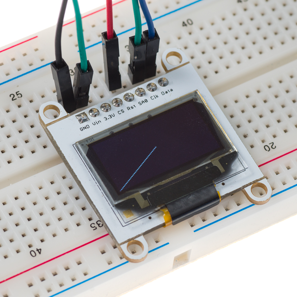
ในตัวอย่างนี้ เส้นจะลากจาก (0,0) ไปยัง (63,31) หรือพูดอีกอย่างคือลากจากมุมล่างซ้ายไปยังจุดกึ่งกลางของหน้าจอ
เราสามารถใช้โค้ดต่อไปนี้เพื่อวาดรูปสี่เหลี่ยมบนหน้าจอ:
#include<Wire.h> //Include Wire library for I2C communication
#define HEIGHT 64
#define WIDTH 128
const int RST = 10; //Assign pin 10 for Reset
int i; //Set variable i as integer
static unsigned char array[1024]; //Buffer array

void setup() {
  pin_init(); //Initialize pins
  initialize_OLED(); //Initialize screen
  memset(array, 0, sizeof(array)); //Initialize array with 0s
  square(117,127,53,63); //Draw square
  Flush(); //Send data
}

void loop() {
}

void pin_init(){
  Serial.begin(9600); //Set baud for serial transmission
  pinMode(RST, OUTPUT); //Set RST as output
}

void initialize_OLED(){
  Wire.begin(); //Initialize I2C interface
  digitalWrite(RST, LOW); //Set RST pin low
  delay(100); //Wait 100 ms
  digitalWrite(RST, HIGH); //Set RST pin high
  Wire.beginTransmission(0x3D); // Start communication with slave
  Wire.write(0x00); //Command stream
  Wire.write(0xAE); //Set display Off
  Wire.write(0xD5); //Set display clock divide ratio/oscillator frequency
  Wire.write(0x80);
  Wire.write(0xA8); //Set multiplex ratio
  Wire.write(0x3F);
  Wire.write(0xD3); //Set display offset
  Wire.write(0x00);
  Wire.write(0x40); //Set display start line
  Wire.write(0x8D); //Set charge pump
  Wire.write(0x14); //VCC generated by internal DC/DC circuit
  Wire.write(0xA1); //Set segment re-map
  Wire.write(0xC0); //Set COM output scan direction
  Wire.write(0xDA); //Set COM pins hardware configuration
  Wire.write(0x12);
  Wire.write(0x81); //Set contrast control
  Wire.write(0xCF);
  Wire.write(0xD9); //Set pre-changed period
  Wire.write(0xF1);
  Wire.write(0xDB); //Set VCOMH Deselected level
  Wire.write(0x40);
  Wire.write(0xA4); //Set entire display on/off
  Wire.write(0xA6); //Set normal/inverse display
  Wire.write(0x20); //Set memory address mode
  Wire.write(0x00); //Horizontal
  Wire.write(0xAF); //Set display on
  Wire.endTransmission(); //End communication with slave
}

/*Function to draw square*/

void square(int x1, int x2, int y1, int y2){

  int x, y; //Define x and y as integer variables

  Wire.beginTransmission(0x3D); //Start communication with slave
  for(x=x1; x<x2; x++){ //Iterate over x range, draw line on y1
    draw_pixel(x,y1); //Draw pixel
  }
  Wire.endTransmission(); //End communication with slave

  Wire.beginTransmission(0x3D); //Start communication with slave
  for(x=x1; x<x2; x++){ //Iterate over x range, draw line on y2
    draw_pixel(x,y2); //Draw pixel
  }
  Wire.endTransmission(); //End communication with slave

  Wire.beginTransmission(0x3D); //Start communication
  for(y=y1; y<y2; y++){ //Iterate over y range, draw line on x1
    draw_pixel(x1,y); //Draw pixel
  }
  Wire.endTransmission(); //End communication with slave

  Wire.beginTransmission(0x3D); //Start communication with slave
  for(y=y1; y<y2; y++){ //Iterate over y range, draw line on x2
    draw_pixel(x2,y); //Draw pixel
  }
  Wire.endTransmission(); //End communication with slave
}

void draw_pixel(int x, int y){
  if((x<0) || (x>=WIDTH) || (y<0) || (y>=HEIGHT)){ //Check for boundaries
    return;
  }
  else{
    array[x+(y/8)*WIDTH] |= _BV((y%8)); //Store pixel in array
  }
}

void Flush(){
 Wire.beginTransmission(0x3D); //Start communication with slave
 Wire.write(0x00); //Command stream
 Wire.write(0x00); //Set lower column start address for page addressing mode
 Wire.write(0x10); //Set higher column start address for page addressing mode
 Wire.write(0x40); //Set display start line
 Wire.endTransmission(); //End communication with slave

 unsigned char twbrbackup = TWBR; //Two wire bit rate register
 TWBR = 12; //Set to 400 kHz

 for(unsigned short q=0; q<(WIDTH*HEIGHT/8); q++){
 Wire.beginTransmission(0x3D); //Start communication with slave
 Wire.write(0x40); //Data stream
 for(unsigned char w=0; w<16; w++){
    Wire.write(array[q]); //Transmit data to be displayed
    q++;
 }
 q--;
  Wire.endTransmission(); //End communication with slave
}
TWBR = twbrbackup;
}
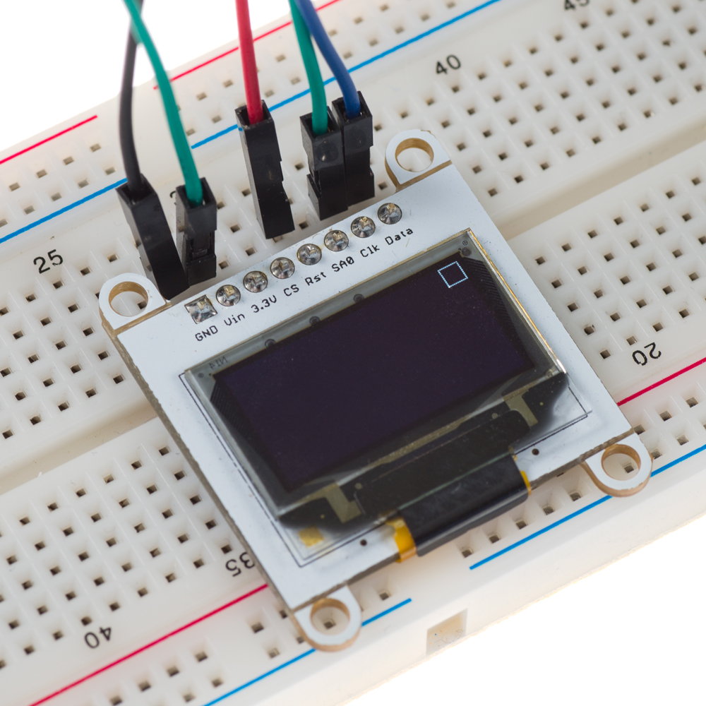
ฟังก์ชันสี่เหลี่ยมรับพารามิเตอร์สี่ตัว ได้แก่ จุดเริ่มต้นและจุดสิ้นสุดบนแกน x และ y เพื่อกำหนดความสูงและความกว้างของสี่เหลี่ยม จากนั้นเส้นสี่เส้นจะถูกวาดแยกจากกันโดยใช้ฟังก์ชัน Pixel อีกครั้ง เส้นแรกที่จะวาดคือเส้นฐานล่างของสี่เหลี่ยมจาก x1-x2 บนแกน y1 เส้นที่สองที่จะวาดคือเส้นด้านบนจาก x1-x2 บนแกน y2 เส้นที่สามคือด้านซ้ายจาก y1-y2 บนแกน x1 และเส้นสุดท้ายคือด้านขวาจาก y1-y2 บนแกน x2 เมื่อ Pixel ของเส้นทั้งหมดถูกเก็บไว้ใน Array แล้ว ฟังก์ชัน Flush จะถูกใช้เพื่อแสดงผลเส้นทั้งสี่ ด้านล่างคือภาพสี่เหลี่ยมขนาด 10 x 10 Pixel ที่อยู่มุมบนขวาของหน้าจอ: วิธีวาดวงกลม?
เราสามารถใช้โค้ดต่อไปนี้เพื่อสร้างวงกลมบนหน้าจอ:
#include<Wire.h> //Include Wire library for I2C communication
#define HEIGHT 64
#define WIDTH 128
const int RST = 10; //Assign pin 10 for Reset
int i; //Set variable i as integer
static unsigned char array[1024]; //Buffer array

void setup() {
  pin_init(); //Initialize pins
  initialize_OLED(); //Initialize screen
  memset(array, 0, sizeof(array)); //Initialize array with 0s
  circle(63,31,10); //Draw circle, (x,y,R)
  Flush(); //Send data
}

void loop() {
}

void pin_init(){
  Serial.begin(9600); //Set baud for serial transmission
  pinMode(RST, OUTPUT); //Set RST as output
}

void initialize_OLED(){
  Wire.begin(); //Initialize I2C interface
  digitalWrite(RST, LOW); //Set RST pin low
  delay(100); //Wait 100 ms
  digitalWrite(RST, HIGH); //Set RST pin high
  Wire.beginTransmission(0x3D); // Start communication with slave
  Wire.write(0x00); //Command stream
  Wire.write(0xAE); //Set display Off
  Wire.write(0xD5); //Set display clock divide ratio/oscillator frequency
  Wire.write(0x80);
  Wire.write(0xA8); //Set multiplex ratio
  Wire.write(0x3F);
  Wire.write(0xD3); //Set display offset
  Wire.write(0x00);
  Wire.write(0x40); //Set display start line
  Wire.write(0x8D); //Set charge pump
  Wire.write(0x14); //VCC generated by internal DC/DC circuit
  Wire.write(0xA1); //Set segment re-map
  Wire.write(0xC0); //Set COM output scan direction
  Wire.write(0xDA); //Set COM pins hardware configuration
  Wire.write(0x12);
  Wire.write(0x81); //Set contrast control
  Wire.write(0xCF);
  Wire.write(0xD9); //Set pre-changed period
  Wire.write(0xF1);
  Wire.write(0xDB); //Set VCOMH Deselected level
  Wire.write(0x40);
  Wire.write(0xA4); //Set entire display on/off
  Wire.write(0xA6); //Set normal/inverse display
  Wire.write(0x20); //Set memory address mode
  Wire.write(0x00); //Horizontal
  Wire.write(0xAF); //Set display on
  Wire.endTransmission(); //End communication with slave
}

/*Midpoint circle algorithm*/

void circle(int x0, int y0, int R){
  int x = R; //Set x equal to radius
  int y = 0;
  int de = 1-x;

  while(x>=y){
    draw_pixel(x+x0, y+y0); //First octant
    draw_pixel(y+x0, x+y0); //Second octant
    draw_pixel(-y+x0, x+y0); //Third octant
    draw_pixel(-x+x0, y+y0); //Fourth octant
    draw_pixel(-x+x0, -y+y0); //Fifth octant
    draw_pixel(-y+x0, -x+y0); //Sixth octant
    draw_pixel(y+x0, -x+y0); //Seventh octant
    draw_pixel(x+x0, -y+y0); //Eight octant
    y++;
    if(de<=0){
      de += 2*y+1;
    }
    else{
      x--;
      de += 2*(y-x)+1;
   }
  }
}

void draw_pixel(int x, int y){
  if((x<0) || (x>=WIDTH) || (y<0) || (y>=HEIGHT)){ //Check for boundaries
    return;
  }
  else{
    array[x+(y/8)*WIDTH] |= _BV((y%8)); //Store pixel in array
  }
}

void Flush(){
 Wire.beginTransmission(0x3D); //Start communication with slave
 Wire.write(0x00); //Command stream
 Wire.write(0x00); //Set lower column start address for page addressing mode
 Wire.write(0x10); //Set higher column start address for page addressing mode
 Wire.write(0x40); //Set display start line
 Wire.endTransmission(); //End communication with slave

 unsigned char twbrbackup = TWBR; //Two wire bit rate register
 TWBR = 12; //Set to 400kHz

 for(unsigned short q=0; q<(WIDTH*HEIGHT/8); q++){
 Wire.beginTransmission(0x3D); //Start communication with slave
 Wire.write(0x40); //Data stream
 for(unsigned char w=0; w<16; w++){
    Wire.write(array[q]); //Transmit data to be displayed
    q++;
 }
 q--;
  Wire.endTransmission(); //End communication with slave
}
TWBR = twbrbackup;
}
ฟังก์ชันวงกลมอ้างอิงจาก Midpoint Circle Algorithm ที่ใช้สร้างวงกลมด้วย Pixel อัลกอริทึมนี้จะวาดทีละ Pixel ในแต่ละเสี้ยว (octant) ของวงกลมโดยอาศัยหลักสมมาตรจนกว่าจะครบวงรอบ และฟังก์ชัน Pixel ก็จะถูกนำมาใช้เพื่อวาดแต่ละจุดของวงกลมทุกครั้งที่ถูกเรียกใช้ในโปรแกรม สามารถดูข้อมูลเพิ่มเติมเกี่ยวกับอัลกอริทึมได้ที่ลิงก์ต่อไปนี้:
โดยการระบุพารามิเตอร์สามตัวให้กับฟังก์ชันวงกลม (จุดศูนย์กลางที่ (x,y) และรัศมี) ตอนนี้เราก็สามารถวาดวงกลมได้เหมือนภาพด้านล่าง:
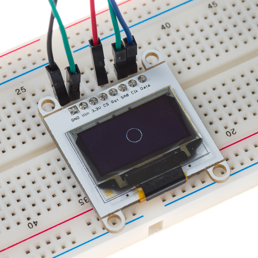
ในตัวอย่างนี้ จุดศูนย์กลางของวงกลมอยู่ที่ (63,31) และมีรัศมี 10 ทำให้เกิดวงกลมที่กลางหน้าจอด้วยรัศมี 10 Pixel
หากเราใช้การแสดงผลแบบ Buffer ที่มีการระบุค่าไว้ล่วงหน้า เราจะสามารถแสดงผลภาพใดๆ ที่เราต้องการบนหน้าจอได้ โค้ดต่อไปนี้แสดงวิธีการดังกล่าว:
#include<Wire.h> //Include Wire library for I2C communication

const int RST = 10; //Assign pin 10 for Reset
int i; //Set variable i as integer
const unsigned char js[] = {
0x00, 0x00, 0x00, 0x00, 0x00, 0x00, 0x00, 0x00, 0x00, 0x00, 0x00, 0x00, 0x00, 0x00, 0x00, 0x00,
0x00, 0x00, 0x00, 0x00, 0x00, 0x00, 0x00, 0x00, 0x00, 0x00, 0x00, 0x00, 0x00, 0x00, 0x00, 0x80,
0xC0, 0xC0, 0xC0, 0xC0, 0xC0, 0xC0, 0xC0, 0xC0, 0x80, 0xC0, 0xC0, 0xC0, 0xC0, 0xC0, 0xC0, 0xC0,
0x80, 0xC0, 0xC0, 0xC0, 0xC0, 0xC0, 0x80, 0xC0, 0xC0, 0xC0, 0xC0, 0xC0, 0x80, 0xC0, 0xC0, 0xC0,
0x80, 0xC0, 0xC0, 0xC0, 0x80, 0xC0, 0xC0, 0xC0, 0x80, 0xC0, 0xC0, 0xC0, 0xC0, 0xC0, 0x80, 0x80,
0x00, 0x00, 0x00, 0x00, 0x00, 0x00, 0x00, 0x00, 0x00, 0x00, 0x00, 0x00, 0x00, 0x00, 0x00, 0x00,
0x00, 0x00, 0x00, 0x00, 0x00, 0x00, 0x00, 0x00, 0x00, 0x00, 0x00, 0x00, 0x00, 0x00, 0x00, 0x00,
0x00, 0x00, 0x00, 0x00, 0x00, 0x00, 0x00, 0x00, 0x00, 0x00, 0x00, 0x00, 0x00, 0x00, 0x00, 0x00,
0x00, 0x00, 0x00, 0x00, 0x00, 0x00, 0x00, 0x00, 0x00, 0x00, 0x00, 0x00, 0x00, 0x00, 0x00, 0x00,
0x00, 0x00, 0x00, 0x00, 0x00, 0x00, 0x00, 0x00, 0x00, 0x00, 0x00, 0x00, 0x00, 0x0E, 0x0F, 0x1F,
0x1F, 0x1F, 0x3F, 0x3F, 0x3F, 0x3F, 0x3F, 0x1F, 0x3F, 0x3F, 0x3F, 0x3F, 0x1F, 0x1F, 0x3F, 0x3F,
0x3F, 0x3F, 0x1F, 0x1F, 0x3F, 0x3F, 0x1F, 0x1F, 0x3F, 0x3F, 0x1F, 0x1F, 0x3F, 0x3F, 0x1F, 0x1F,
0x3F, 0xFF, 0xFF, 0xFF, 0xFF, 0xFF, 0xFF, 0xFF, 0xFF, 0xFF, 0xFF, 0xFF, 0xFF, 0xFF, 0xFF, 0xFF,
0x00, 0x00, 0x00, 0x00, 0x00, 0x00, 0x00, 0x00, 0x00, 0x00, 0x00, 0x00, 0x00, 0x00, 0x00, 0x00,
0x00, 0x00, 0x00, 0x00, 0x00, 0x00, 0x00, 0x00, 0x00, 0x00, 0x00, 0x00, 0x00, 0x00, 0x00, 0x00,
0x00, 0x00, 0x00, 0x00, 0x00, 0x00, 0x00, 0x00, 0x00, 0x00, 0x00, 0x00, 0x00, 0x00, 0x00, 0x00,
0x00, 0x00, 0x00, 0x00, 0x00, 0x00, 0x00, 0x00, 0x00, 0x00, 0x00, 0x00, 0x80, 0x40, 0x80, 0x60,
0x50, 0xA0, 0xA8, 0x50, 0xA0, 0x5C, 0xA4, 0x48, 0xA8, 0x50, 0xA6, 0x58, 0x90, 0x64, 0x58, 0xA4,
0x58, 0x24, 0x98, 0x68, 0xA8, 0x54, 0x68, 0x22, 0x50, 0xA4, 0x48, 0xB4, 0xA0, 0x5C, 0x94, 0x48,
0x94, 0x68, 0xA4, 0x50, 0x58, 0xA4, 0x58, 0x94, 0x24, 0x58, 0xA4, 0x58, 0xA0, 0x58, 0x04, 0x00,
0x54, 0xFF, 0xFF, 0xFF, 0xFF, 0xFF, 0xFF, 0xFF, 0xFF, 0xFF, 0xFF, 0xFF, 0xFF, 0xFF, 0xFF, 0xFF,
0x84, 0x00, 0x60, 0x2A, 0x90, 0x64, 0x58, 0xA4, 0x58, 0x24, 0x98, 0x68, 0xA8, 0x54, 0x68, 0x24,
0x24, 0x58, 0xA4, 0x58, 0xA4, 0x48, 0x94, 0x68, 0x90, 0x6A, 0xD4, 0x28, 0x20, 0xD4, 0x68, 0x12,
0x50, 0xA4, 0x48, 0xB4, 0xA4, 0x18, 0x50, 0x08, 0x00, 0x00, 0x00, 0x00, 0x00, 0x00, 0x00, 0x00,
0x00, 0x00, 0x00, 0x00, 0x00, 0x00, 0x00, 0x00, 0x00, 0x00, 0x00, 0x04, 0x25, 0x7E, 0x9A, 0xE5,
0x76, 0x59, 0xCA, 0xB5, 0x9D, 0x6A, 0xFD, 0x92, 0xDA, 0x61, 0x60, 0xA0, 0x80, 0xC0, 0x20, 0xC0,
0x40, 0xA0, 0x80, 0xE0, 0x40, 0xC0, 0x40, 0xA0, 0x80, 0xC0, 0x20, 0xC0, 0x40, 0xA0, 0x80, 0xE0,
0x40, 0xC0, 0x40, 0xA0, 0x80, 0xC0, 0x20, 0xC0, 0x40, 0xC0, 0x80, 0x60, 0xC0, 0xA0, 0x80, 0xC0,
0xC0, 0x6D, 0x6F, 0xDF, 0xBF, 0xAF, 0x7F, 0xCF, 0xBF, 0xBF, 0xDF, 0x6F, 0x7F, 0xDF, 0x9F, 0xAF,
0xC0, 0x40, 0x80, 0xA0, 0xC0, 0x40, 0x40, 0xC0, 0xC0, 0x40, 0x40, 0xC0, 0xC0, 0x80, 0xE0, 0x40,
0x40, 0xC0, 0x40, 0xA0, 0x80, 0xC0, 0x20, 0xC0, 0x40, 0xC0, 0x80, 0xC0, 0x00, 0xC0, 0xC0, 0x00, 0xC0, 0x00, 0x80, 0x00, 0x00, 0x00, 0x00, 0x00, 0x00, 0x00, 0x00, 0x00, 0x00, 0x00, 0x00, 0x00, 0x00, 0x00, 0x00, 0x00, 0x00, 0x00, 0x00, 0x00, 0x00, 0x00, 0x00, 0x00, 0x00, 0x80, 0x80, 0x81, 0xC1, 0xC3, 0xC2, 0xC2, 0x85, 0x87, 0xC6, 0x87, 0x09, 0x0F, 0x02, 0x0F, 0x05, 0x0F, 0x06, 0x06, 0x07, 0x05, 0x0F, 0x09, 0x05, 0x0F, 0x06, 0x06, 0x07, 0x0D, 0x07, 0x0C, 0x07, 0x05, 0x0F, 0x0A, 0x05, 0x0F, 0x06, 0x06, 0x07, 0x0D, 0x07, 0x0C, 0x07, 0x05, 0x0F, 0x0A, 0x05, 0x0F, 0x06, 0x06, 0x0F, 0xCA, 0xEE, 0xFB, 0xF3, 0xFD, 0xFB, 0xEE, 0xEE, 0xFB, 0xEE, 0xF3, 0xFB, 0xFE, 0xFB, 0xCE, 0x03, 0x0E, 0x0B, 0x0E, 0x03, 0x0E, 0x0A, 0x07, 0x03, 0x0E, 0x0B, 0x0E, 0x03, 0x0E, 0x0A, 0x07, 0x07, 0x0D, 0x07, 0x0C, 0x07, 0x05, 0x0F, 0x0A, 0x0E, 0x0B, 0xB5, 0xEF, 0x6A, 0xFF, 0x7B, 0xEC, 0xFF, 0x69, 0xFF, 0xAA, 0xB7, 0xFC, 0x6E, 0xF8, 0xE0, 0x80, 0x00, 0x00, 0x00, 0x00, 0x00, 0x00, 0x00, 0x00, 0x00, 0x00, 0x00, 0x00, 0x00, 0x00, 0x00, 0x00, 0x00, 0x80, 0xFF, 0xFF, 0xFF, 0xFF, 0xFF, 0xFF, 0xFF, 0xFF, 0xFF, 0xFF, 0xFF, 0xFF, 0xFF, 0xFE, 0x00, 0x00, 0x00, 0x00, 0x00, 0x00, 0x00, 0x00, 0x00, 0x20, 0x78, 0x7C, 0xDC, 0xFC, 0x7E, 0xF8, 0xFE, 0xBC, 0xFC, 0xFE, 0xF6, 0xDC, 0xEC, 0xF6, 0xFC, 0xFE, 0xFE, 0xBC, 0x7A, 0xFC, 0xFC, 0xFE, 0xE8, 0xFE, 0xFC, 0xBE, 0xEC, 0x10, 0x34, 0xFE, 0xFF, 0xFF, 0xFF, 0xFF, 0xFF, 0xFF, 0xFF, 0xFF, 0xFF, 0xFF, 0xFF, 0xFF, 0xFF, 0xFF, 0xD8, 0x00, 0x6C, 0xFC, 0xFC, 0xFA, 0xBE, 0xFC, 0xEC, 0xF6, 0xFC, 0xFE, 0xFE, 0x7C, 0x7A, 0xFC, 0xFC, 0x7E, 0xF6, 0xFC, 0xFE, 0xDC, 0xFC, 0xEE, 0xBE, 0xFE, 0xFF, 0xE7, 0xFE, 0x7F, 0xFB, 0x7F, 0x7E, 0x6F, 0x3F, 0x3B, 0x1E, 0x1F, 0x0F, 0x03, 0x01, 0x00, 0x00, 0x00, 0x00, 0x00, 0x00, 0x00, 0x00, 0x00, 0x00, 0x00, 0x00, 0x00, 0x00, 0x00, 0x00, 0x00, 0x00, 0x00, 0x3F, 0x7F, 0xFF, 0xFF, 0xFF, 0xFF, 0xFF, 0xFF, 0xFF, 0xFF, 0xFF, 0xFF, 0xFF, 0xFF, 0xF8, 0xF0, 0xF0, 0xF0, 0xE0, 0xF0, 0xE0, 0xF0, 0xE0, 0xF0, 0xE0, 0xE0, 0xE0, 0xF0, 0xF0, 0xF0, 0xE0, 0xF0, 0xE0, 0xF0, 0xE0, 0xF0, 0xE0, 0xF0, 0xE0, 0xF0, 0xE0, 0xE0, 0xE0, 0xF0, 0xF0, 0xF0, 0xE0, 0xF0, 0xE0, 0xE0, 0xF0, 0xF0, 0xF0, 0xFE, 0xFF, 0xFF, 0xFF, 0xFF, 0xFF, 0xFF, 0xFF, 0xFF, 0xFF, 0xFF, 0xFF, 0x7F, 0x7F, 0x1F, 0x00, 0x00, 0x00, 0x00, 0x00, 0x00, 0x00, 0x00, 0x00, 0x00, 0x00, 0x00, 0x00, 0x00, 0x00, 0x00, 0x00, 0x00, 0x00, 0x00, 0x00, 0x00, 0x00, 0x00, 0x00, 0x00, 0x00, 0x00, 0x00, 0x00, 0x00, 0x00, 0x00, 0x00, 0x00, 0x00, 0x00, 0x00, 0x00, 0x00, 0x00, 0x00, 0x00, 0x00, 0x00, 0x00, 0x00, 0x00, 0x00, 0x00, 0x00, 0x00, 0x00, 0x00, 0x00, 0x00, 0x00, 0x00, 0x00, 0x00, 0x00, 0x00, 0x00, 0x01, 0x03, 0x03, 0x07, 0x03, 0x03, 0x07, 0x07, 0x07, 0x07, 0x0F, 0x07, 0x0F, 0x07, 0x0F, 0x07, 0x07, 0x0F, 0x07, 0x0F, 0x0F, 0x07, 0x0F, 0x07, 0x07, 0x0F, 0x07, 0x0F, 0x0F, 0x07, 0x0F, 0x07, 0x07, 0x0F, 0x07, 0x0F, 0x0F, 0x07, 0x0F, 0x07, 0x07, 0x0F, 0x07, 0x0F, 0x0F, 0x07, 0x0F, 0x07, 0x07, 0x07, 0x0F, 0x07, 0x07, 0x07, 0x07, 0x03, 0x07, 0x07, 0x03, 0x01, 0x01, 0x01, 0x00, 0x00, 0x00, 0x00, 0x00, 0x00, 0x00, 0x00, 0x00, 0x00, 0x00, 0x00, 0x00, 0x00, 0x00, 0x00, 0x00, 0x00, 0x00, 0x00, 0x00, 0x00, 0x00, 0x00, 0x00, 0x00, 0x00, 0x00, 0x00, 0x00, 0x00, 0x00, 0x00, 0x00, 0x00, 0x00, 0x00, 0x00, 0x00, 0x00, 0x00, 0x00, 0x00, 0x00, 0x00, 0x00, 0x00, 0x00, 0x00, 0x00, 0x00 };   void setup() {
  pin_init(); //Initialize pins
  initialize_OLED(); //Initialize screen
  pattern(); //Display image
}
  void loop() {
}
  void pin_init(){
  Serial.begin(9600); //Set baud for serial transmission
  pinMode(RST, OUTPUT); //Set RST as output
}
  void initialize_OLED(){
  Wire.begin(); //Initialize I2C interface
  digitalWrite(RST, LOW); //Set RST pin low
  delay(100); //Wait 100 ms
  digitalWrite(RST, HIGH); //Set RST pin high
  Wire.beginTransmission(0x3D); // Start communication with slave
  Wire.write(0x00); //Command stream
  Wire.write(0xAE); //Set display Off
  Wire.write(0xD5); //Set display clock divide ratio/oscillator frequency   Wire.write(0x80);
  Wire.write(0xA8); //Set multiplex ratio
  Wire.write(0x3F);
  Wire.write(0xD3); //Set display offset
  Wire.write(0x00);
  Wire.write(0x40); //Set display start line
  Wire.write(0x8D); //Set charge pump
  Wire.write(0x14); //VCC generated by internal DC/DC circuit
  Wire.write(0xA1); //Set segment re-map
  Wire.write(0xC8); //Set COM output scan direction
  Wire.write(0xDA); //Set COM pins hardware configuration
  Wire.write(0x12);
  Wire.write(0x81); //Set contrast control
  Wire.write(0xCF);
  Wire.write(0xD9); //Set pre-changed period
  Wire.write(0xF1);
  Wire.write(0xDB); //Set VCOMH Deselected level
  Wire.write(0x40);
  Wire.write(0xA4); //Set entire display on/off
  Wire.write(0xA6); //Set normal/inverse display
  Wire.write(0x20); //Set memory address mode
  Wire.write(0x00); //Vertical
  Wire.write(0xAF); //Set display on
  Wire.endTransmission(); //End communication with slave
}

void pattern(){
  for(i=0; i<1024; i++){
  Wire.beginTransmission(0x3D); //Start communication with slave
  Wire.write(0x40); //Data stream
  for(unsigned char x=0; x<16; x++){
     Wire.write(js[i]); //Transmit data to be displayed
     i++;
  }
  i--;
  Wire.endTransmission(); //End communication with slave
 }
}
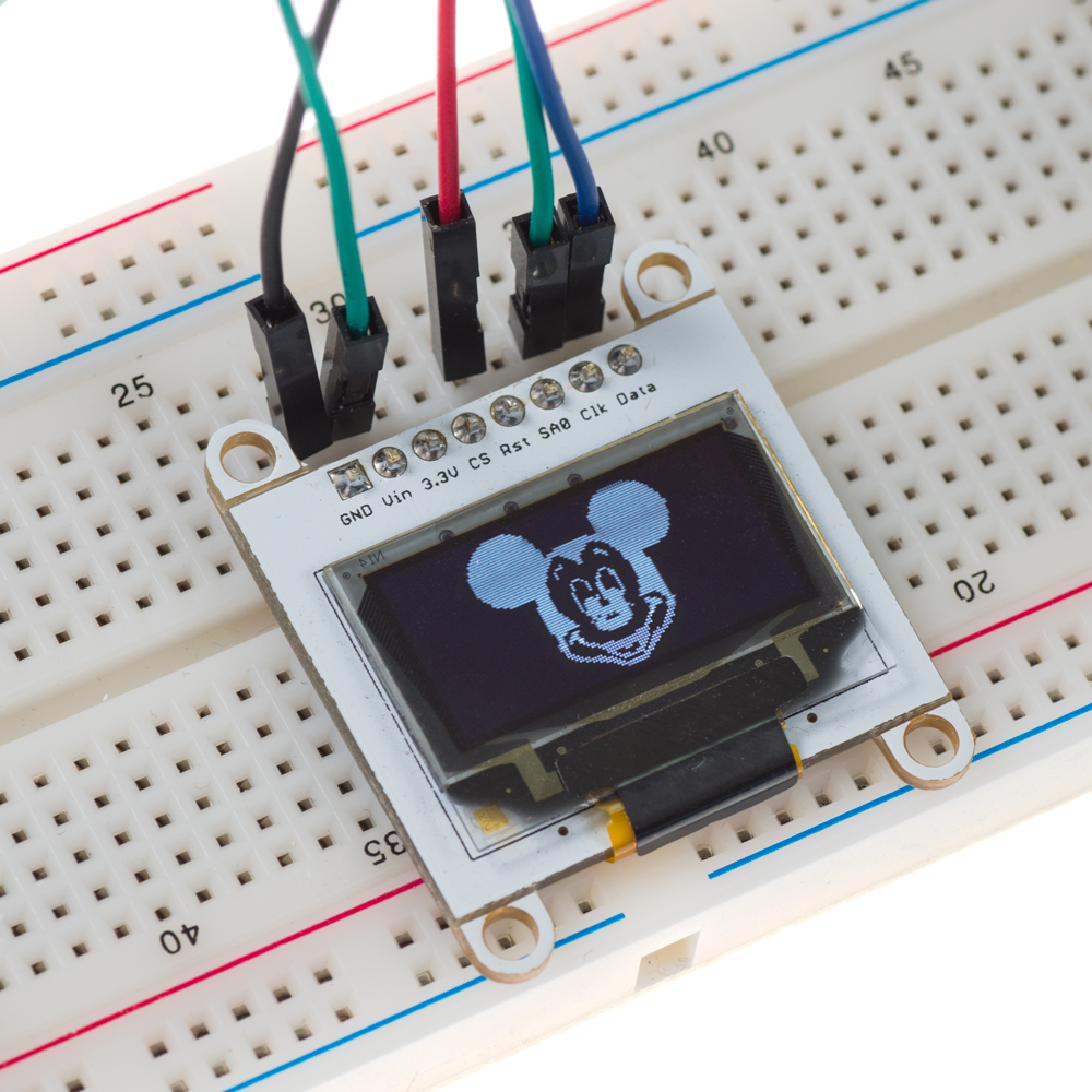
ในตัวอย่างก่อนหน้านี้ เราจะใช้ฟังก์ชัน Pixel เพื่อสร้างรูปทรงต่างๆ โดยการวางแต่ละ Pixel ลงในตำแหน่งที่ระบุภายใน Array จากนั้นเราจะใช้ฟังก์ชัน Flush เพื่อแสดงข้อมูลของ Array บนหน้าจอตามรูปทรงที่ต้องการ ในกรณีนี้ แทนที่จะสร้างค่าของ Array buffer ผ่านการใช้ Iteration เราจะให้ข้อมูล Array จำนวน 1024 Byte ที่เป็นตัวแทนของภาพที่เราต้องการแสดงผล วิธีนี้ช่วยให้เราแสดงผลภาพใดๆ ก็ได้ตามต้องการ แต่ก็มีข้อจำกัดบางประการ แล้วเราจะได้ค่าเหล่านี้มาได้อย่างไร? ขั้นแรกเราต้องหาภาพที่ต้องการแสดงก่อน เราต้องแน่ใจว่าภาพนั้นมีขนาด 128x64 (ความละเอียดของหน้าจอเรา) และเป็นภาพแบบ Monochrome (ขาวดำ) ผมนำภาพนี้มาจากอินเทอร์เน็ต:

เมื่อเราเลือกภาพได้แล้ว เราต้องแปลงจาก JPEG เป็น Bitmap ทำได้ง่ายๆ โดยเปิดรูปภาพใน Paint แล้วบันทึกเป็น Monochrome bitmap (.bmp) เราสามารถใช้ซอฟต์แวร์กราฟิกอื่นๆ ในการแปลงไฟล์ภาพได้หากต้องการ จากนั้น ด้วยความช่วยเหลือของ LCD Assistant, เราจะสามารถโหลดภาพ BMP และบันทึกเป็นไฟล์ CPP ได้ ซึ่งจะสร้างค่า Array ที่เราต้องการนำไปใช้ในโค้ดเพื่อแสดงผลภาพ เมื่อโปรแกรมทำงาน เราจะได้ผลลัพธ์ดังนี้:
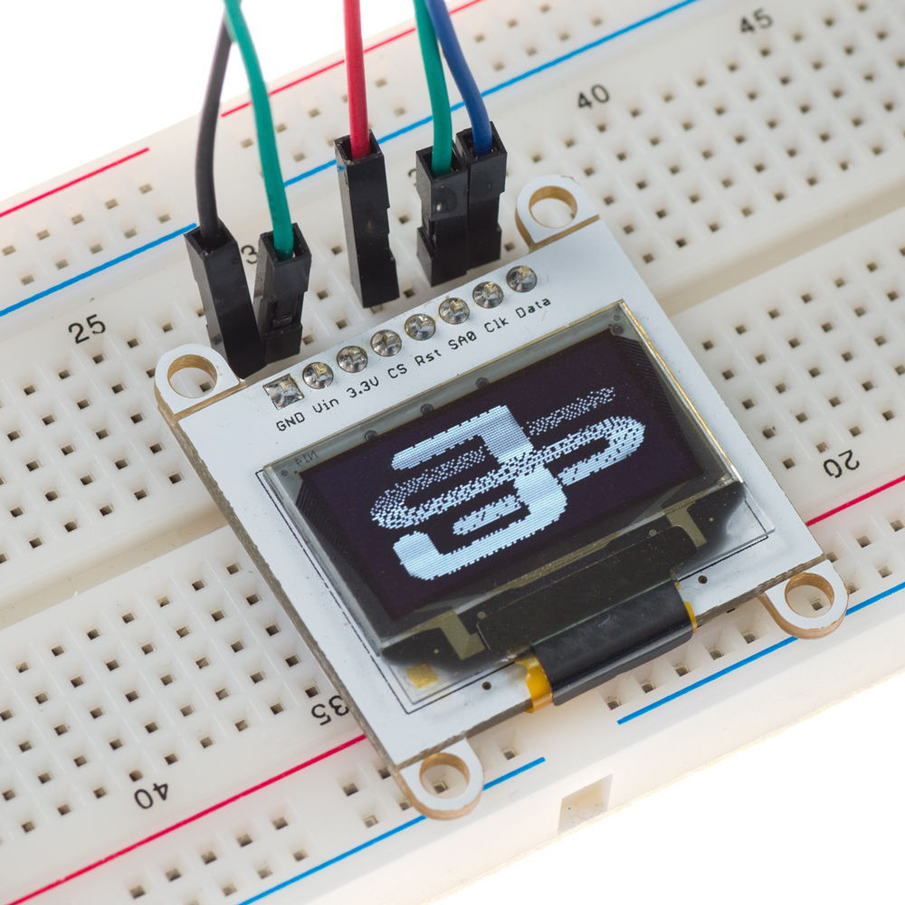
นี่คืออีกหนึ่งตัวอย่างพร้อมโลโก้บริษัทของ Jaycon System:
หากคุณมีคำถามใดๆ เกี่ยวกับบทเรียนนี้ อย่าลังเลที่จะโพสต์ความคิดเห็น ส่งอีเมลมาหาเรา หรือโพสต์ในฟอรัมของเราได้เลย
สนับสนุนเพื่อรับ Source Code หรือแอปพลิเคชันสำหรับโปรเจกต์นี้
ประเมิน Project
เอาฟอร์มยาวออกจากท้ายหน้า Project แล้ว เหลือเป็นปุ่มให้กดไปกรอกหน้าเดียว ตัวใหญ่ เว้นบรรทัดเยอะ อ่านง่ายกว่า
รีวิวจากคนใช้งานจริง
ถ้าเคยสั่งงาน เคยอ่านหน้านี้แล้วได้ประโยชน์ หรือมีข้อเสนอแนะ ฝากรีวิวไว้ได้เลย
ยังไม่มีรีวิวบนหน้านี้ ถ้าเคยใช้งานหรือมีข้อเสนอแนะ เขียนเป็นคนแรกได้เลย